By Ray Robinson
VK2ILV
E-Mail robinson@srsuna.shlrc.mq.edu.au
Brief History
The Type K command sets were conceived in 1934 by Dr. Frederick H. Drake, chief designer
of the Aircraft Radio Corporation. At this time, the Army Air Corps was using the SCR-183
and the Navy the very similar GF/RU short range TRF radios. In 1937, Dr. Atherton Noyes
from General Radio was employed to design the transmitters. Five years were spent,
designing, testing, and improving the radios. In 1939 the Navy tested the prototype, and
immediately bought production models. They were the RAT (13.5-20 mcs and 20-27 mcs
receivers) followed by RAV (190 kc to 27 mc) and ordered GT/RBD transmitters in June 1940.
The Army, after suffering failure of its new crystal controlled SCR-240 design, ordered
them in June 1940 as the SCR-274N (N meaning Navy). The Aircraft Radio Corporation then
began making the ARA/ATA design as well as the SCR-274N. In 1942-43 an improved version
called the AN/ARC-5 was introduced for the Navy. The VHF designs began to appear late in
the war and had extensive civilian use after 1945. The design was eventually extended to
become the AN/ARC-12 and AN/ARC-60 VHF sets used in the Korean war and up until about
1960.
The "Command" radio is a description of the radio function, rather than a specific model. The "Command" function was to communicate between aircraft. The "Liaison" function was to communicate back to base. However, functions often become blurred in use, and even though there were several different models and generations of "Command" radios, one particular model has become popularly known as "Command sets".
The Command set is a general title for several groups of receivers and transmitters
used in World War 2, which are more specifically called the (United States Army Air Force)
SCR-274N, (United States Navy) ATA/ARA, and the (United States Navy) AN/ARC-5. They
were used for Air to Air, Air to Ground communications and for receiving Navigation
signals. They are a unique design of that era, in that most radios would use a band switch
to change to a different frequency band, whereas this design selects a completely
different receiver or transmitter. After the war, they were still used. I have one that
was used in Australian Civil Aircraft which was reconditioned in 1956.
Here is more complete list
The Army SCR-274N series radios were available in black crackle paint, or natural
aluminium finish. The Navy ARC-5 were in black crackle paint. Externally they looked
identical in appearance, and only differed in colour and frequency coverage. Internally
they were very similar, with only minor differences, apart from the obvious ones relating
to the frequency. The SCR-274N series had BC-454 type names and the ARC-5 had R25
and T20 type names for the receivers and the transmitters. The adapter drawer on the front
had a different knob and label for Army and Navy. Some of the low frequency receivers had
a different antenna connection so that a loop aerial could be connected. The
circuits were almost the same, with only a few small changes because of the frequency
coverage. The valve line up was the same, except that some ARC-5 receivers used a 12SF7
second IF valve instead of the 12SK7 which was more common.
Here is a list of differences
They are a very nicely made radio. The metal parts are aluminium pressings, with rivets and riveted nuts. The capacitors, chokes and transformers are in cylindrical metal cans with mica insulators. The resistors are mounted on mica tag strips. The wire is a cotton covered type, sometimes with a tropical proofing. All the connectors use mica sheet. The RF coils, IF transformers, and dynamotor all plug in.
They can be operated locally, using a tuning knob and an adapter. Normally, they would be remotely controlled using a control box. The control box had electrical connections for the Gain and MCW/OFF/CW switch, and a flexible tuning shaft for the frequency.
There was a modification published in the post war magazines which involved adding local controls and a coaxial antenna connector. This involved drilling holes in the receiver and removing some parts. A large percentage of the command sets available today have been modified in this way, and are difficult to restore to their original condition. Collectors will pay considerably less for modified sets as the original ones are more desirable.
AN/ARC-5
This series of radios is an updated version of the ATA/ARA and SCR-274N radios. They were
used by the US Navy for the latter part of World War 2 and were their main aircraft
communication radio. They were fitted in many different bomber and fighter aircraft types
for communication between aircraft, navigation, and communication back to base. A fighter
would usually have 1 receiver and 1 transmitter fitted. A bomber would often have 3
receivers and 3 transmitters fitted. These radios were available in black wrinkle finish.
A VHF version was introduced late in the war and this was available in an unpainted
finish.
There are six receivers: the R-23 (0.19-0.55 mcs), R-23A (0.19-0.55 mcs), R-24 (0.52-1.5 mcs), R-25 (1.5-3 mcs), R-26 (3-6 mcs), and the R-27 (6-9.1 mcs). The receivers were remotely mounted and controlled, with a C-26 one receiver control box, a C-27 one receiver control box with tuning locked, a C-38 three receiver control box, all with tuning locked and a homing receiver control. When the receivers were remotely controlled, a plug in on the front, called an adapter, was used to enable the remote control. This adapter, the MX-21, was merely a link inside the box. When the receiver was used in local control, the adapter C-24 had a volume control and ON/OFF/BFO switch. An ARC 6743 local tuning knob was used for local tuning. An MX-20 power adapter was available that had a connector on the front so that power was available for other equipment, usually an homing receiver. There was also an MX-19 audio adapter for instrument landing equipment. The receivers were mounted in racks, with several bays, the MT-7 held one receiver, the MT-63 held two receivers, the MT-65 held three receivers, and the MT-67 held four receivers. Each receiver had its own dynamotor.
There are eight transmitters: T-15 (0.5-0.8 mcs), T-16 (0.8-1.3 mcs), T-17 (1.3-2.1 mcs), T-18 (2.1-3 mcs), T-19 (3-4 mcs), T-20 (4-5.3 mcs), T-21 (5.3-7 mcs), and the T-22 (7-9.1 mcs). The transmitters were similarly remotely mounted and controlled, with the C-29 control box, which controlled from 1 to 4 transmitters. The transmitters were mounted in racks, with several bays, the MT-69 held one transmitter, the MT-71 held two transmitters, the MT-73 held three transmitters, and the MT-75 held four transmitters. There was an RE-2 antenna changeover relay box, that also had a RF antenna current meter. The power for the transmitters came from the MD-7 modulator which also has a DY-8 dynamotor to generate the high voltage.
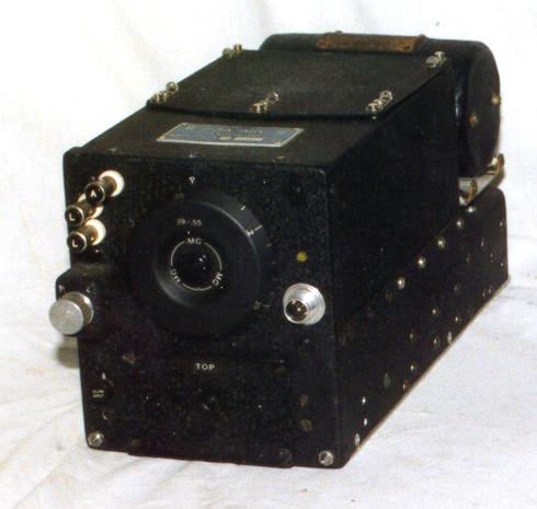 R-23 and R-23A Receivers |
R-23 and R-23A Receivers The R-23 only had one aerial terminal, whereas the R-23A has 2 extra terminals for a loop connection, and a spline shaft control to switch between them, by using the C-25 remote switch. (I'm looking for one of these.) The photograph shows a screw on cap for protection the spline shaft when it is not used. I'll put up a photo of an R-23 when I manage to purchase one. The frequency coverage is 190-550 kcs and the Intermediate Frequency is 85 kcs. The valve line-up is: 12SK7 RF amp, 12K8 mixer, 12SK7 first IF amp, 12SF7 second IF amp, 12SR7 detector, AGC, and CW oscillator, 12A6 audio output. The one in the photograph is an R-23A, and is serial number 1475. |
It came from J.R. in very good condition, and only needed its heaters rewired for 28v. The modified adapter was replaced, with an unmodified MX-21. This LF receiver, could also be fitted with 2 other adapters. It could be fitted with an MX-19 audio adapter for instrument landing equipment (I'm looking for one of these). It could also be fitted with a MX-20 power adapter for supplying power to other equipment.
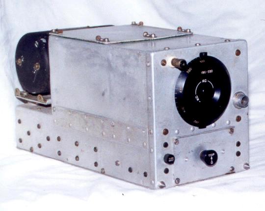
 R-24 Receiver |
R-24 Receiver Frequency coverage: 0.5-1.5 mcs Intermediate Frequency: 239 kcs Valves: 12SK7 RF amp, 12K8 mixer, 12SK7 first IF amp, 12SF7 second IF amp, 12SR7 detector, AGC, and CW oscillator, 12A6 audio output. This R-24 did not have a name plate, so I have etched one from sheet brass, tin plated it, and filled it with blue paint. Consequently, I don't know the serial number. When I bought this for $30 from BP, it was in reasonable condition. The front panel was bent where it had been dropped, and it only needed some panel beating and minor respraying of the lower left hand corner. The valve heaters were rewired to 28v and it was aligned. It had no faults! The modified adapter was replaced, with a new MX-20 power adapter for supplying power to an ARR-1 homing receiver. |
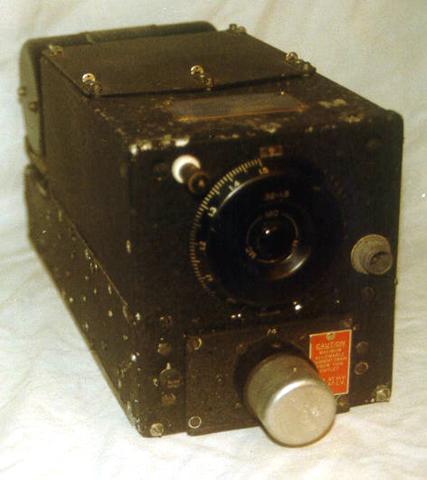
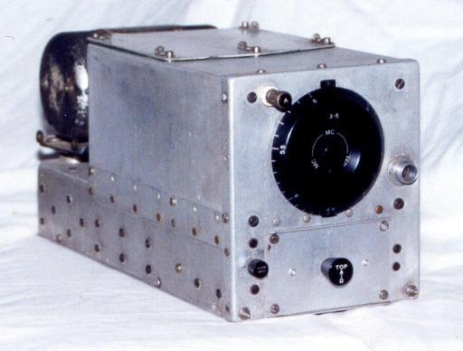
 R-25 Receiver |
R-25 Receiver The frequency coverage is 1.5 - 3 mcs and the Intermediate Frequency is 705 kcs. The valve line-up is: 12SK7 RF amp, 12K8 mixer, 12SK7 first IF amp, 12SF7 second IF amp, 12SR7 detector, AGC, and CW oscillator, 12A6 audio output. The one in the photograph has the "stabilised" stamp, and is serial number 3152. It came from L.G. in very good condition, and only needed its heaters rewired for 28v. The modified adapter was replaced, with an unmodified MX-21 . The valve cover (with the red plate) has a small dial underneath it for fitting to a C-26 single receiver control box. |
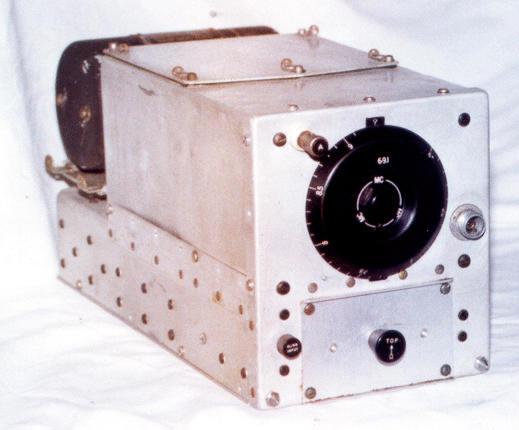
 R-26 Receiver |
R-26 Receiver Frequency coverage: 3.0-6.0 mcs Intermediate Frequency: 1415 kcs Valves: 12SK7 RF amp, 12K8 mixer, 12SK7 first IF amp, 12SF7 second IF amp and AGC, 12SR7 detector, and CW oscillator, 12A6 audio output. This one has serial number 1182 and has the stabilised stamp. (I'm looking for a C-24 control adapter so that I can use this one in local control). |
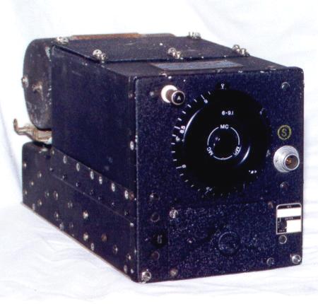 R-27 Receiver |
R-27 Receiver Frequency coverage: 6.0-9.1 mcs Intermediate Frequency: 2830 kcs Valves: 12SK7 RF amp, 12K8 mixer, 12SK7 first IF amp, 12SF7 second IF amp and AGC, 12SR7 detector, and CW oscillator, 12A6 audio output. Serial number 6192. This one was bought from M.R. for $20 in March 1997. It had wires soldered to the dynamotor pins, and needed 2 capacitors replaced. The heaters were rewired to 28v and the set aligned. It has the S stamp on the front to indicate a "Stabilised" unit. The paint is in very good condition. |
SRC-274N
This series of radios are basically the same as the Navy radios in the ARA and ATA range.
They were adopted by the Signal Corps and were their main aircraft communication radio for
most of World War 2. The N suffix to the SCR-274N signifies a Navy design. They were used
in many different bomber and fighter aircraft types for communication between aircraft. A
fighter like the P-38 Lightning, and P-51 Mustang would usually have 1 receiver and 1
transmitter fitted. A bomber like the B-17 Flying Fortress, the B-24 Liberator, and the
B-29 Super Fortress would often have 3 receivers and 3 transmitters fitted. These radios
were available in black and unpainted finish.
There are four receivers: the BC-453 (0.19-0.55 mcs), BC-946 (0.52-1.5 mcs), BC-454 (3-6 mcs), and the BC-455 (6-9.1 mcs). The receivers were remotely mounted and controlled, with a BC-473 one receiver control box, a BC-496 two receiver control box, or a BC-450 three receiver control box. Each receiver had its own dynamotor. The receivers were mounted in racks, with several bays, the FT-233 held one receiver, the FT-227 held two receivers, the FT-220 held three receivers, and the FT-264 held four receivers. When the receivers were remotely controlled, a plug in on the front, called an adapter was used to enable the remote control. This adapter, the FT-230, was merely a link inside the box. When the receiver was used in local control, the adapter FT-260 had a volume control and ON/OFF/BFO switch. An MC-237 local tuning knob was used for local tuning. An FT-310 adapter was available that had a connector on the front so that power was available for other equipment. The BC-946 usually had this type of adapter.
There are four transmitters: BC-696 (3-4 mcs), BC-457 (4-5.3 mcs), BC-458 (5.3-7 mcs), and the BC-459 (7-9.1 mcs). The transmitters were similarly remotely mounted and controlled, with the BC-451 control box, which controlled from 1 to 4 transmitters. The transmitters were mounted in racks, with several bays, the FT-234 held one transmitter, the FT-226 held two transmitters, the FT-276 held three transmitters, and the FT-331 held four transmitters. There was a BC-442 antenna changeover relay box, that also had a RF antenna current meter. The power for the transmitters came from the BC-456 modulator which also has a DM-33 dynamotor to generate the high voltage. The handheld microphone used was a T-17.
 BC-453 Receiver |
BC-453 Receiver Frequency coverage: 190-550 kcs Intermediate Frequency: 85 kcs Valves: 12SK7 (VT131) RF amp, 12K8 (VT132) mixer, 12SK7 (VT131) first IF amp, 12SK7 (VT131) second IF amp, 12SR7 (VT133) detector and CW oscillator, 12A6 (VT134) audio output. Made by: Western Electric serial number #68444. |
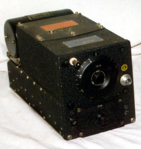
 BC-946 Receiver |
BC-946 Receiver This was a later addition to the receiver range, and that is why the BC number is much higher. Frequency coverage: 0.5-1.5 mcs Intermediate Frequency: 705 kcs Valves: 12SK7 (VT131) RF amp, 12K8 (VT132) mixer, 12SK7 (VT131) first IF amp, 12SK7 (VT131) second IF amp, 12SR7 (VT133) detector and CW oscillator, 12A6 (VT134) audio output. This one is shown with an FT-230 remote control adapter. It was normal to have an FT-310 power adapter fitted for supplying power to a homing receiver. (I don't have an FT-310 yet.) This set is made by Colonial Radio serial number 5393. |
 BC-454 Receiver |
BC-454 Receiver Frequency coverage: 3.0-6.0 mcs Intermediate Frequency: 1415 kcs Valves: 12SK7 (VT131) RF amp, 12K8 (VT132) mixer, 12SK7 (VT131) first IF amp, 12SK7 (VT131) second IF amp, 12SR7 (VT133) detector and CW oscillator, 12A6 (VT134) audio output. Made by: Colonial Radio #4718. |
 BC-455 Receiver |
BC-455 Receiver Frequency coverage: 6.0-9.1 mcs Intermediate Frequency: 2830 kcs Valves: 12SK7 (VT131) RF amp, 12K8 (VT132) mixer, 12SK7 (VT131) first IF amp, 12SK7 (VT131) second IF amp, 12SR7 (VT133) detector and CW oscillator, 12A6 (VT134) audio output. Made by Colonial Radio #1480. This one is shown with an FT-230 remote control adapter. (I'm looking for a FT-260 adapter so that I can run this one in local control.) |
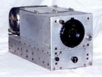
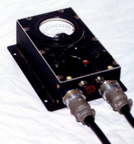 I-84B Receiver Test Set |
I-84B Receiver Test Set This is a test unit for bench testing SCR-274N receivers. It has a meter with a select switch that can measure 5 parameters in the receiver. The switch selects Input Voltage, Input Current, Screen Voltage, Plate Voltage, and Cathode Current. The meter scale only has one set of calibration marks and most readings are mid-scale for normal conditions. It also has a built in remote control function, similar to the normal remote control box. It has a CW/OFF/MCW switch, and a Gain control. There is a phone jack for speaker, headphone, or output meter connection. One plug is for 28 VDC input, the other connects to the receiver, rear connector. There is also a fuse. This unit has serial number 736. It is brand new and came in its original cardboard box. The I-84A test set has the same functions, except it has 5 separate meters and no select switch. |
I had to modify some Utilux connectors to fit, and you can see the bright ferrules in the photograph. I turned these up on a small lathe. Connectors are always difficult to find. I have used black cable on this unit. Some connectors have an open style rear shell, and the wires exit individually. The original wire was a cotton covered type, and was usually laced into a cable form.
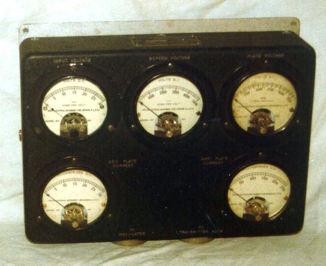 I-85A Transmitter Test Set |
I-85A Transmitter Test Set This is a test unit for bench testing SCR-274N transmitters. It consists of a box with 5 meters in which monitor the transmitter parameters. The test set is placed between the transmitter and the modulator. The meters show the Input Voltage (0-30v), Oscillator Plate Current (0-30ma), Screen Voltage (0-500v), Plate Voltage (0-750v) and Amplifier Plate Current (0-250ma). The I-85B test set only has one meter and a switch to select the range. When I got this test set, it was missing the top left hand meter which is used for measuring the input voltage. I made a new one from 3 meters of the same type. One provided the case to match the others, one provided the movement, and the other provided the scale. |
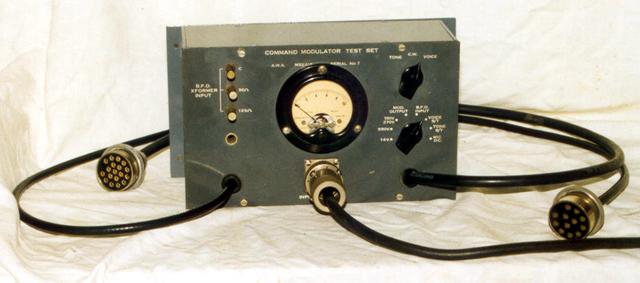 M-52215 Modulator Test Set |
M-52215 Modulator Test Set The Modulator Test Set is a small grey box that contains a meter and 2 switches, which are used for testing the functions of the BC-456 modulator. The test box has 2 cables with plugs that connect to the modulator. One cable connects to the modulator output socket (normally connected to the transmitter), and the second cable connects to the modulator control socket (normally connected to the transmitter control box). |
These cables power the modulator and connect to the various modulator parts for monitoring voltages and levels. There is a main power connector for the 28 volt input, and 3 terminals to connect an audio input source. There are 2 switches for selecting the functions to be tested. The meter is calibrated with a single scale that reads 0 to 10. There is also a phone jack for listening to the modulator output. The test set is marked serial number 7.
I have looked in the SCR-274N and AN/ARC-5 manuals that I have, and there is no mention of any modulator test set, only the receiver and transmitter test sets. The A.W.A. manual on the SCR-274N has no information on any test sets at all. This test set must be an Australian design and manufacture. It is made by A.W.A. (Amalgamated Wireless Australia) and the components and construction are consistent with their practices.
There are 2 main control switches. The emission switch at the top right hand side selects TONE/CW/VOICE which performs the same function as the switch on the transmitter control box. The function switch on the lower right hand side selects the various functions to be tested. Several switch positions act as a volt meter, and the other positions use an internal bridge rectifier and the meter acts as a level meter. The terminals on the left hand side are for connection to an audio signal generator, which has a transformer output. The microphone DC goes through this. The input terminals are labelled BFO which is the name that A.W.A. used for their audio signal generator in the 1940s.
The first position of the function switch, is labelled 14V. This measures the input voltage to the modulator, and reads 4 for 14 volts input and 8 for 28 volts input. The test set can therefore test 14 or 28 volt modulators. The second switch position is labelled 550V and measures the high voltage output from the dynamotor. The meter reads 5.5 for 550 volts output. The third switch position is labelled 270/150V and measures the low voltage output. When the emission switch is set to TONE or VOICE, the regulator in the modulator is switched on, and the voltage drops to 150 volts. The meter reads 8 for 270 volts and 4 for 150 volts. The fourth switch position labelled MOD. OUT and measures the level of audio output from the modulator. The meter reads 3 for TONE, 2 for CW, and 1 for VOICE. The fifth switch position labelled BFO is used to measure and set the input level from the signal generator. This only reads 1 at maximum output from the BFO (which seems low, and the modulator output is low as well). The sixth switch position is labelled VOICE S.T. and measures the level of the audio tone that is sent to the receiver as a side tone. (A "side tone" is some of the transmit audio that is sent to the receiver, so you can hear what you are transmitting). The meter reads 10 for TONE, 0 for CW, and 3 for VOICE. The seventh switch position is labelled TONE S.T. and measures the level of the audio tone that is sent to the receiver as a side tone. The meter reads 8 for TONE, 8 for CW, and 0 for VOICE. The eighth switch position is labelled MIC DC and measures the microphone power supply voltage. The meter indicates 3 in this position.
When I found this unit at a junk sale, it had no box or cables, but was in reasonable condition. I made a box similar in style to the other command test sets, which have a rear flange for wall mounting. I painted the box the same grey as the front panel. I then traced the circuit, and made some guesses about the modulator connections. The meter is slightly too large and covers part of the front panel engraving. I added the cables and connectors, checked all the components, and then applied power. The test set worked first time. The BFO input terminals were disconnected inside. I have reconnected them, but may not have it quite right, as the input levels are low.
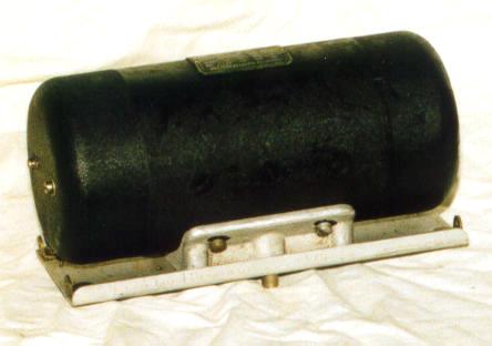
 DM-32 Receiver Dynamotor |
DM-32 Receiver Dynamotor The command sets have a small dynamotor that sits on the back deck of the receiver. It takes 28 VDC (there was a 12 VDC version) and generates 250 VDC for the valves. It has a 3 pin connector under it, so that it can be unplugged for maintenance. It sits on 4 rubber mounts, to reduce vibration. These mounts are usually removed from the receivers and they are hard to find. I always need more. The dynamotors can have labels of DM-32 for the SCR-274N sets, or DY-2A/ARR-2 for the ARC-5 (and ARR-2) sets. |
 DM-33 Transmitter Dynamotor |
DM-33 Transmitter Dynamotor The transmitters use one dynamotor for their High Tension supply. It is continuously rated at 575 volts dc at 160 ma. They only need one, as only one transmitter is on at a time. The dynamotor is located on the BC-456 modulator. |
References
The Command Set Story, Gordon Elliot White, CQ, November 1964, P37-40.
Command Sets, Gordon Elliot White, CQ, October 1965, P34-37.
Command Sets, CQ, Cowan Publishing Corp, 1957, Library of Congress 58-59924.
Electric Radio In Uniform, Command Sets Part I, Walt Hutchens, Electric Radio,
Number 11, P4-7,20-24.
Electric Radio In Uniform, Command Sets Part II, Walt Hutchens, Electric Radio,
Number 12, P4-7, 26-29.
On the Air with the Command Set Triplets, Jim Hanlon, Electric Radio, Number 74, P4-9, 39.
On the Air with the Command Set Transmitters, Jim Hanlon, Electric Radio, Number 75, P4-9,
38.
Visitors to this page since 20 February 2000
Back to Your Articles Index Page.
Army Radio Sales Co. Home Page.