0
item(s)
Cart is empty
Language
|
Home
::
|
By Major Breckinridge S. Smith USAF (Retired)
E-Mail smithab11@comcast.net
Web Site:
http://home.comcast.net/~smithab11/
Please Note: Army Radio Sales Co. and this Article's authors are not responsible for any damages or personal injury whatsoever, that may occur as a result of information provided here. This Article is published in good faith and as far as we can tell accurate. Make sure you understand the instructions before starting. Modifications to military radio sets may invalidate the suppliers warranty and reduce the re-sale value of the radio.
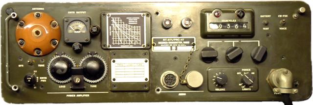
| Variable Frequency Control For The PRC-47 |
| Overview: A simple mod requiring one 100K pot and 20 inches of wire. Anyone can accomplish this mod that has a soldering iron. This mod is stable and has been tested on several radios. Credit: Background: Terms Used: |
|
|
 Modification Points |
|
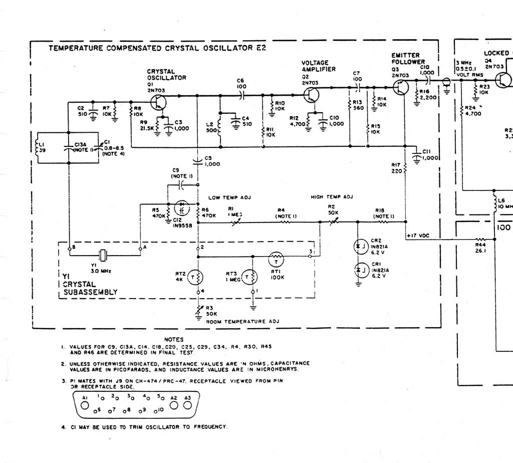 Circuit Diagram |
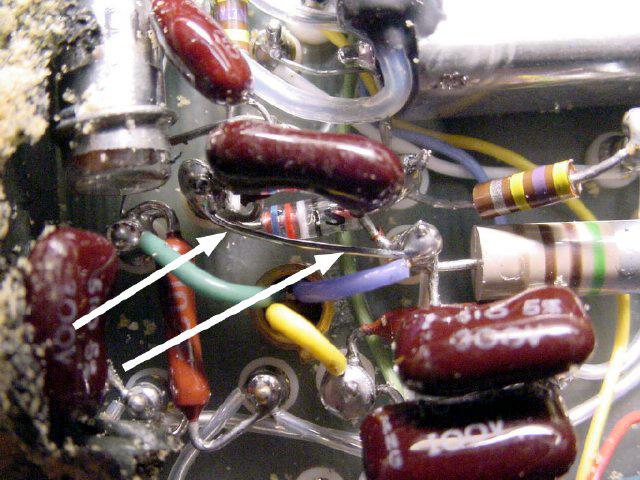
The mod consists of two changes in the circuit of the R.F. Oscillator module. All you have to do is to lift the end of a resistor (ARROW) and solder on a wire, and put a wire jumper across a small cap C-5 (ARROW) in the Oscillator module. By lifting the wire you are disconnecting the temperature compensation circuit for the crystal oscillator, you will then provide a voltage via a 100K pot mounted on the front panel of the radio to swing C-12 a crystal varicap. By soldering a wire across C-5, which is a "series" cap you are effectively removing it from the circuit and thus increasing the operating value of varicap C-12 making its value higher and more effective.
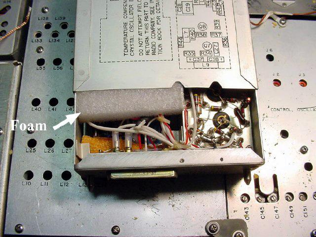
Target Module, last one in the right rear. Marking on the top is
Oscillator R.F. Unscrew the module retaining screws from the bottom of the
radio, remove the module and then remove the module cover, the cover slides
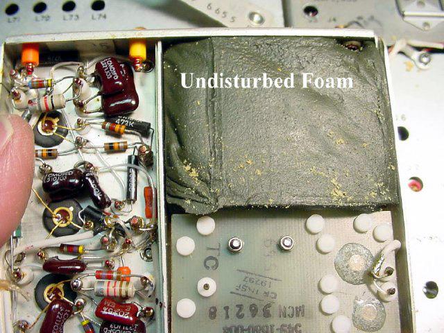
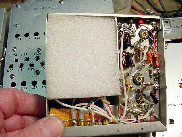
off. Take out the foam. Be sure and remove foam from the correct side.
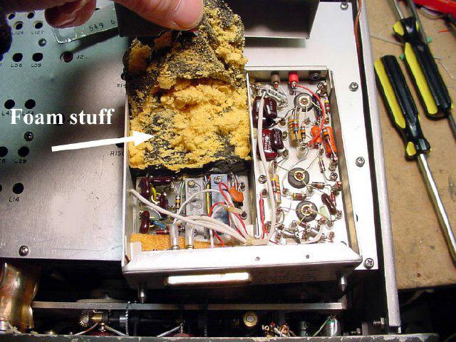 Remove The Foam, Correct Side |
|
 This Is The Wrong Side |
|
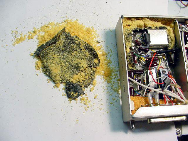 The Old Foam |
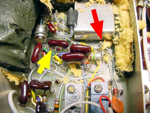 The First Target, 470K Resistor |
|
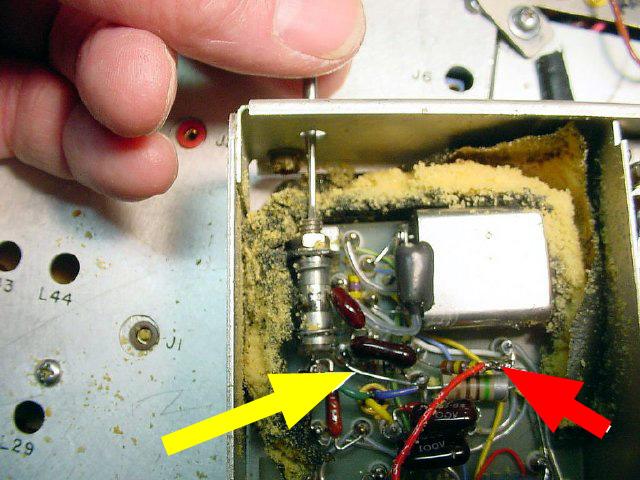
The first target "Red Arrow" is the end of R-6 a 470K
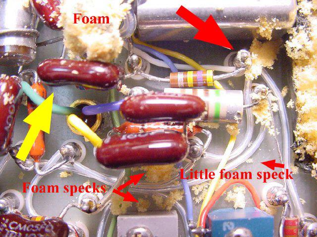
resistor. (Yellow-Violet-Yellow) Unsolder the end shown by the "Red Arrow" and lift the resistor end. Do not unsolder any other wires on this terminal. The "Yellow arrow" points to C-5. The resistor is now lifted free. Connect a 5 inch wire to the free end and then cover the resistor and wire connection with heat shrink for insulation and strain relief. Moving on, the 2nd target , "Yellow Arrow" ,C-5 a 1000 pf ceramic cap. You should be able to see the value printed on the side. |
 Un-Soldering The 470K Resistor |
|
 Covering The Resistor & Wire |
|
 The Second Target |
 Soldering The Wire Across The Cap |
|
Solder a wire across the cap leads. A lead cut from a
resistor makes a nice wire. Find the connector which is in the bottom of the oscillator module. You are going to use a spare pin to supply the variable voltage from a panel mounted pot. Select a spare pin on the module connector and connect the new wire from the free end of R-6 to this pin. This way you will be able to provide a variable voltage to the module for frequency control and still be able to plug and unplug the module without any extra wires. I used pin 4, its a nice even number and easy to get to. I used some type 77 ferrite beads to de-couple the wire but ran tests without the beads and the mod functioned OK. Diagram of the module connector located in the bottom of the module, see diagram below. |
See the picture of the connector J9 underneath the chassis showing the spare pins available. I choose pin four, the second pin over from the large connectors A2 and A3. It all ready has my Violet wire connected. This is a good choice to prevent shorting out the connection. This picture is for information only you will connect the pin later.
 The Connector |
|
 Module Connector Diagram |
|
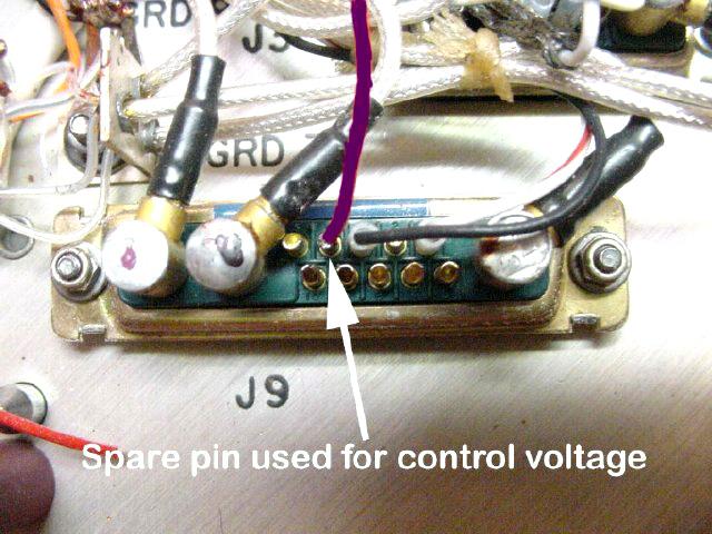 Connector J9 |
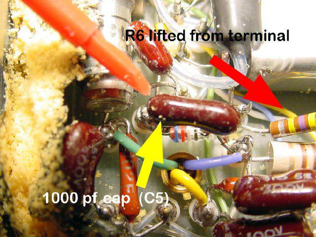
 R6 and C5 Photo |
|
Photo showing the red wire connected to R-6 and the short
across C-5. Photo also depicts how the master Osc. is trimmed for frequency,
No trimming was necessary on any of the radios tested. Just leave the trim
alone. Leave The Trimmer Alone! Replace the foam with a new piece or else carefully pick up all of the little pieces of foam that you removed previously and glue it all back. Replace the cover and trim foam as necessary. Remove the 115 volt fuse holder (originally suggested by Dennis Starks), this will create a hole, the hole will be used for mounting the frequency control pot. Heat shrink the unsoldered leads and secure with a cable tie. |
 Replace The Foam |
|
 Replacing The Cover |
|
 Removing The Fuse Holder |
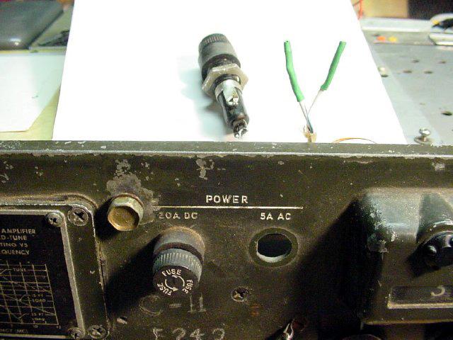 Ex-Fuse Hole Now For The Pot |
|
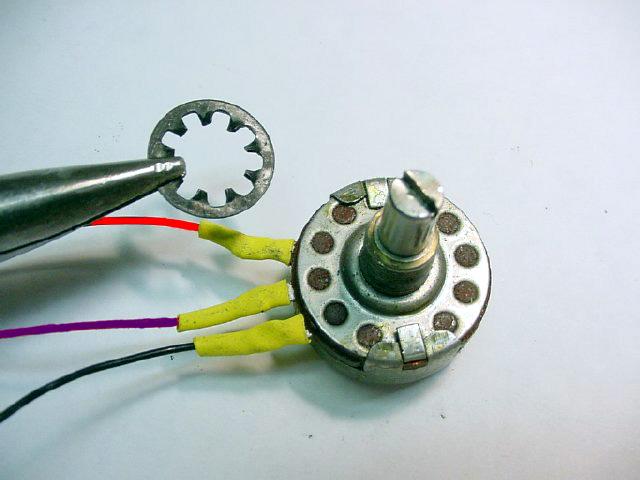
Connect 3 wires to the pot. Use a lock washer to keep the
pot from moving once it is installed. I used a 100 K pot but 50K , 250K will
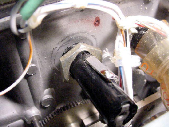
work, play with it. See the picture of the rear of the pot mounted in the hole, Violet the centre tap supplies the variable voltage to pin 4 of J9 (Osc module socket), the left red wire will go to the 20 volt voltage source and the far right wire (black) is grounded to the chassis. A small solder lug is used for the ground wire of the pot and as a strain relief for the other wires. |
 Connect 3 Wires To The Pot |
|
 Install The Pot |
|
 Rear Of The Pot |
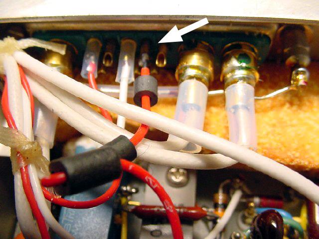
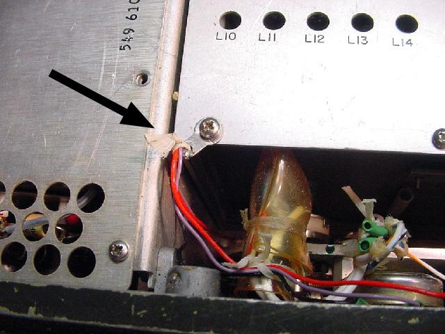
Next target area. Top arrow points to the voltage distribution strip. The bottom arrow points to J-9 the oscillator chassis socket. Snake the wires from the pot down and behind the front panel, secure with a solder lug and cord or cable tie, and then run through the chassis grommet.
 Wire Strain Relief |
|
 Next Target Area, See Arrows |
|
 Snaking The Wires |
 Test Jig |
|
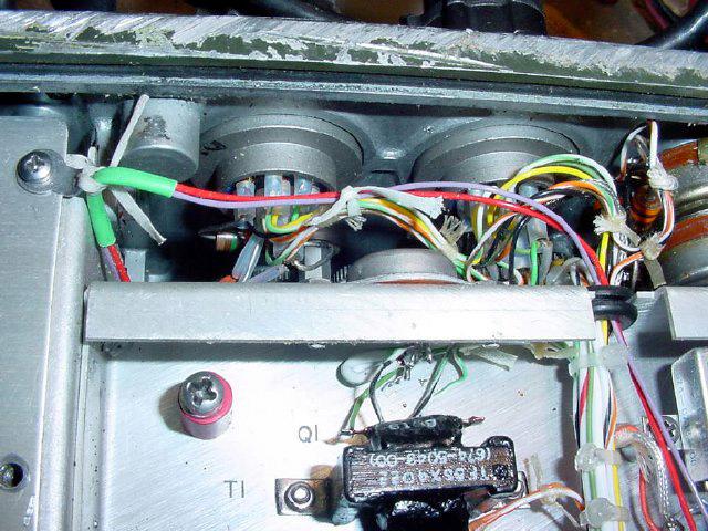
My test jig that sat on my bench for a month. Amazingly
stable. Really neat installation which is typical of my work. Connect the RED end wire of the pot that you installed to terminal 4 of TB-4,this point is going to supply regulated 20 volts DC from the radio's power supply. The bottom of the picture is the rear of the radio. On some radios TB-4 was not marked on the chassis. Connect the centre wire of your pot to pin 4 of J-9, see diagram below. Put a piece of heat shrink on the wires. Its usually easier to put the heat shrink on the wire first and then solder the wire. |
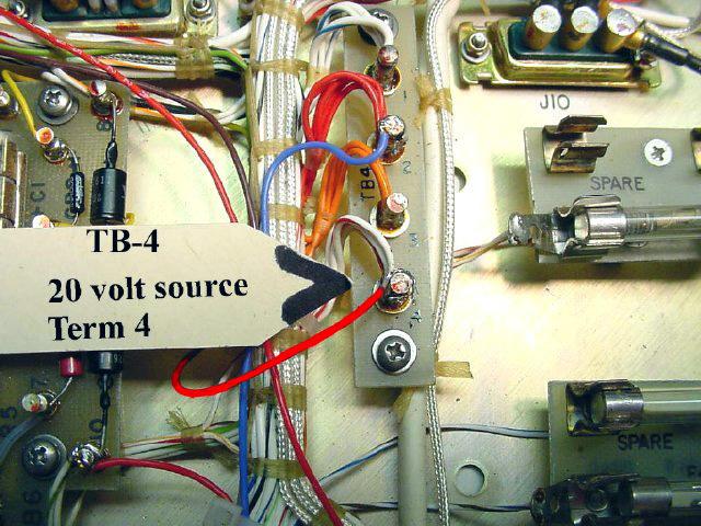 Connecting The Red Wire |
|
Connecting The Centre Wire To J9 |
|
Module Connector Diagram |
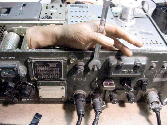
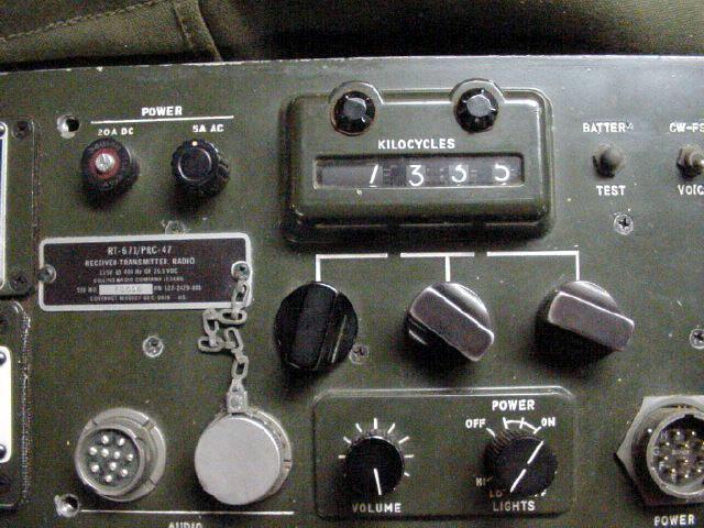 Knob Installed |
|
All there is to do is to install the knob. To check calibration and find the 12 o'clock or centre position for your pot tune in a time standard, I like CHU on 7335 Kcs. |
Visitors to this page since 03 January 2003
Back to Your Articles Index Page.
Army Radio Sales Co. Home Page.
