|
Home
::
|
Model AQST East German 'HRO' Receiver
|
As many readers will know, the National HRO receiver - or at least, its design concept of an all-band receiver with plugin coil packs and a large indirectly calibrated tuning dial was widely copied in several countries, both before and particularly during World War II. Possibly the best-known of these copies are the German KST made by Korting Radio, and the R4 by Siemens, both wartime production and widely employed as monitoring receivers by the German services. Less well-known are two further versions of the KST made only in small numbers and most unlikely to be met with today. |
| The first of these was manufactured by the Wega company in Stuttgart; the second by an organisation founded by one Alfred Ulrich shortly after the end of W.W.II in the East German town of Bernburg, appropriately named 'Funkwerkstatten (radio workshops) Bernburg' or 'FWB' for short. In the following year, the FWB introduced a new HRO style receiver designated 'Model AQST', an acronym for 'Allwellenempfanger mit Quarzfilter und Storaustastung, (all-band receiver with crystal filter and noise silencer), which they appear to have manufactured for at least five years. Several production runs of this receiver appeared, including a special 'export series' for the People's Republic of China in 1951, incorporating sundry design modifications including a change of chassis material from tinplate to aluminium-bronze alloy in later versions. The AQST appears to have been designed by or for the East German state postal and telecommunication authority and seems unlikely to have been intended for non-commercial use; undoubtedly it was adopted by similar authorities in other Iron Curtain countries at the time. In recent years however, some of these receivers have found their way into the hands of radio amateurs and HRO fans in continental Europe, and in May 1993 I acquired one, complete with its matching AC power supply and six of the eight plug-in coil packs designed for use with the set. My receiver is one of the later series, with aluminium-bronze chassis, front panel and cabinet. | |
|
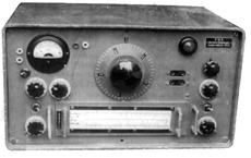
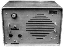
External Appearance The front panel of the receiver retains a remarkably traditional-looking appearance despite the introduction of several extra facilities. During the same period, the American National Company introduced its HRO-7 and HRO-50 models which bore little outward physical resemblance to their wartime predecessors except for the unmistakable tuning dial. Unlike many of its wartime ancestors however, all valves and components of the AQST are of Eastern European origin, mostly German, though my own set contains some Czech-made (Tesla) capacitors and Russian MLT resistors, which may be later replacements. A more detailed consideration of the receiver's components and constructional features appears later in this article. |
| Externally, the AQST comprises a chassis and front panel assembly in cast aluminium-bronze alloy, secured inside a wrap-around cabinet by six long bolts passing through the front panel. The separate AC power supply ('Netzgerat') is housed in a similar but smaller cabinet. Carrying handles were originally fixed to the sides of these cabinets to assist with transportation, though these have vanished on my own units. The entire equipment is painted in a satin finish grey-green, which appears to be original. All operating controls are mounted on the front panel, whilst antenna, ground and power connections are available on the chassis backdrop. The 4mm sockets visible on the front panel in the photograph were added by a previous owner, and are thus strictly unofficial, but have been retained as they serve a useful purpose by duplicating the antenna, ground and AGC monitoring points on the back of the chassis. | |
|
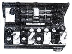
Circuitry Like the original National HRO, the AQST is a single conversion superhet containing two RF amplifier stages, separate mixer and local oscillator, two IF amplifier stages, BFO, 2nd detector/AGC and AF output stages. Three additional valves operate the noise silencer and S-meter amplifier circuitry. The separate dedicated AC power supply also contains - unlike the type 697 for the HRO - a substantial loudspeaker, and additional outlets are provided for 600 Ohm line and 4000 Ohm headphones. The principal changes incorporated in the AQST receiver itself may be summarised as shown below. The 'works' below chassis convey a marked visual contrast to the standard HRO. Much of the wiring is run in heavily varnished cotton insulation in varying shades of brown which makes circuit tracing rather difficult in the absence of official information. Extensive use is made of local bus bars and vertical tag boards; most de-coupling capacitors are metal-cased tubular types bolted directly to chassis. |
| Resistors are generally of a red or green-enamelled finish with printed
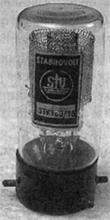
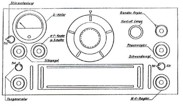
resistance values, including some non standard values such as 0.32M Ohm. Valves are mostly East German versions of the classic 'Stahlrohren' (literally 'steel tubes') on F8 bases. These have glass bulbs sprayed with a metallic screen coating instead of the black all-metal bulbs of their West German counterparts, and consist mainly of RF pentodes EF11, 12, 13 and 14 plus one each of ECH11, EBF11 and EL11. The gas stabiliser, type STV100-25z, has a curious 4-pin side contact base of pre-war Germanic origin see photo, and the 'Glimmrohre' protecting the antenna circuits resembles a small festoon lamp. A 468kHz plug-in crystal unit is employed in the crystal phasing circuit. The plug-in coil units are of heavy cast construction in-filled with unglazed ceramic insulation on which the coil contacts are mounted, very solid and substantial compared to the 4 separate light metal cans which comprise a standard HRO coil unit. Frequency calibration relative to dial readings (0 to 500) is displayed on horizontal charts extending the full width of the coil unit and, like the original HRO, every receiver appears to have been individually calibrated. It was noticed, incidentally, that despite their obvious constructional differences, standard HRO coil packs fit the coil slot in the AQST. The tuning gang and dial mechanism are excellent copies of the American originals; the gang is modelled on the pre-war style of HRO tuning capacitor and appears to be rustproof. An S-meter on-off facility is not provided, the meter remaining in circuit at all times. The switch occupying the site of the HRO meter switch provides the noise blanker on-off facility in the AQST. The AGC switch moves from left to right of the coil-box, the former AGC switch position being supplanted by a separate BFO on-off control. The original B+ (HT) on/off facility is incorporated in the AF gain control, and like the HRO, should be turned off prior to coil changing. Performance
compared |
|
|
Conclusions The AQST offers several additional features that would have been considered desirable in the heyday of the National HRO, including the stabilised local oscillator supply and noise silencer described above. The power supply arrangements are much improved and the integral loudspeaker is in my view a great operating convenience. The coil boxes, containing all four units in one solid casting, also represent a considerable improvement over the originals, although I am told that the National coil packs for their HRO-50 and HRO-60 receivers are of similar design - I cannot confirm this however, as I have never seen any. The availability of AGC in conjunction with the BFO - whether by accident or design in my set proved useful when listening to amateur SSB signals. |
| However, whilst the AQST offers these additional benefits and as such, may
be regarded as technically superior to the original HRO, in practice it is not, in my
opinion, noticeably more sensitive, selective or stable than its National predecessor, and
seems more prone to cross-modulation and front-end overload on strong signals. Image
suppression characteristics would be similar to those of the National HRO up to 30MHz and
increasingly poor above, up to 45MHz. Also, like all members of the HRO family, the AQST receiver, together with its associated power supply, heavy connecting cables and large wooden coil storage box, plus auto-transformer, occupy a good deal of space which, as visitors to my shack will testify, is at a premium at G8LIU! This consideration alone means that I shall probably not keep my AQST for much longer. I have not come across any further examples of Model AQST in the UK, though I imagine there are others about; I have no production statistics for the receiver, so I have no idea how many were made. However, from correspondence with a colleague in Germany (who kindly sent me a copy of the user manual for the set), it appears that the AQST is still fairly common over there and does not seem to be very highly regarded, possibly on account of the shortcomings described above. I am also informed that the founder of the 'FWB' was thedesigner of the AQST. AQST principal changes |
|
|
||||||||||||||||||||
Reference Visitors to this page since 1 March 1999 |
Back to Your articles Index Page.
Army Radio Sales Co. Home Page.

