0
item(s)
Cart is empty
Language
|
Home
::
|
By Jerry Proc VE3FAB
E-Mail: jerry.proc@sympatico.ca
Website: http://jproc.ca/ve3fab/
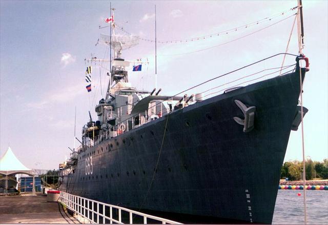
HMCS Haida is one of 27 ships originally built by Britain and Canada, this ship is the
last surviving example of her type. Haida served in Europe during W.W.II. and was sent on
two tours of duty during the Korean conflict.
For more information on the Haida, or the restoration work displayed, Please contact:
Jerry Proc jerry.proc@sympatico.ca
| Length | 377 feet |
| Beam | 38 feet |
| Displacement when full | 3000 tons |
| Built by | Vickers-Armstrong, Newcastle-on-Tyne, England |
| Top Speed | 36.5 knots, Driven by two Parsons steam turbines, 22,000 SHP each |
| Main armament | two pairs or 4" guns, one 3" 50 cal radar controlled gun |
| Commissioned | August 30, 1943 and paid off in October of 1963 |
In the summer of 1992, I started to make regular visits to HMCS Haida in order to assist with the operation of the ship's amateur radio station VE3CGJ. One day, a visitor wanted to see the inside of a transmitter. While removing the access panel, the handle broke so I decided to take the panel home and fix it there. In the weeks that followed, I continued to repair small items. By season's end in October, I took home several of the Marconi CSR5 general coverage receivers in order to restore them as a winter project. That's how it all began - quite innocently. Little did I know what would develop over time.
After four years of intensive effort, I can safely state that the radio restoration project, is for all practical purposes, complete. Enhancements and maintenance to keep all this vintage gear operational will, however, continue into the foreseeable future.
There are some statistics associated with the restoration. The fours years of effort can be translated into approximately 1400 hours aboard the ship and hundreds and hundreds of uncounted hours at home repairing, building and researching. In 1994, Jim Brewer, one of Haida's volunteers, came on-stream to assist with wiring and his hours have been included in the total. Jointly, that represents about 171 Saturdays worth of work. To rebuilt the radio remote control system alone, it took 10 months and 4,000 wiring slices. A total of $2,850 was expended on direct costs and I contributed $1,650 towards 'soft' expenses over the period. Some of the direct costs were offset with one-time donations from radio clubs around Toronto, however, the Skywide Amateur Radio Club of Etobicoke, Ontario continues to assist consistently. This support is greatly appreciated and I hope that it continues into the future. 'Friends of Haida', a registered charitable organisation which provides funding for many of the activities aboard Haida, was also instrumental in offsetting some of the costs.
In total, there are 107 pieces in the radio system including four crypto units, speakers, antennas and power supplies. In 1992, there were only 32 pieces on hand when I arrived on the scene. Junction boxes, cables and speaker enclosures had to be built. Missing equipment had to be located along with service/operating manuals. Currently, the AN/SRC 501 HF radiotelephone is the only missing piece of radio gear and I doubt whether the four missing crypto units will ever be acquired. During the four year time span, a 184 page document titled 'Radio Systems Aboard Haida' was produced. This required two years of research to obtain the initial information and took roughly a year to process a major update. Work continues on a similar document relating to sonar, radar and IFF systems used aboard the ship and the RCN in general.
Today, the following systems are operational |
| UHF - All of the seven UHF channels have been made operational, however, since the equipment was designed to operate in the 200 to 400 Mhz military band, all transmitters have been fitted with dummy loads to prevent inadvertent transmissions. |
| VHF - The ships TDQ transmitter is capable of operating in the 2 metre amateur band. Unfortunately, no one uses AM on 2 metres any more so this capability sits idle. The companion receiver, the model RCK monitors transmissions from Toronto Island airport and the audio is piped to the bridge and operations room to simulate a naval communications environment for our visitors. Whenever Haida came into the St. Lawrence Seaway system, a temporary VHF set was fitted for purposes of communicating with other vessels within the Great Lakes. This function is now implemented using a solid state marine transceiver which is hidden from view but connected to the remote control system. Transmissions from pleasure boats on Lake Ontario and the Canadian Coast Guard station in Toronto are also piped to the bridge and operations room. |
| Remote Control - All of the fourteen radio Remote Control Units can switched to any of the Haida's twelve transmitter/receiver pairs. In addition, there is a complete intercom facility between the bridge, the operations room and two radio rooms. |
| Radio-Teletype (RTTY) - Most of the radioteletype system is functioning. In today's world of digital communications, 60 WPM RTTY transmissions are not very common, but it's still possible to copy W1AW, the headquarters station of the American Radio Relay League in Hartford Connecticut. |
| High Frequency (HF) - The original four operating positions which used to receive the CW broadcast have been restored complete with functioning CW keys and typewriters. One of the Marconi CM11 transmitters in Radio 2 will remain unserviceable because the trunking for the open wire transmission line was razed many years ago and cannot be recreated without incurring a great expense. |
| Direction Finding - The Marconi FM12 MF/DF is now functioning. Unfortunately the UDP 501 radar D/F receiver will remain unserviceable until a service manual can be located. |
Was the expenditure of time worth it? You bet it was! In retrospect, the outcome turned out to be one of the most fulfilling and rewarding endeavours of my life. I also have to thank my kind and wonderful wife Dori, who graciously understood why it was necessary to devote so much time and effort towards this project. Over the years, many individuals donated equipment, parts, and information. They are simply too numerous to list here, but I'm most grateful for their interest and participation in the project. In particular, I would especially like to thank the Royal Canadian Navy for their sizeable contributions to the restoration. My thanks are also extended to Cdr. Bob Willson who provided me with much needed support over the duration of the period. Bob will be missed since he will retire in December of 1996 after ten excellent years of service as Haida's Captain. It was also a great privilege to have been able to recreate a historical display which illustrates RCN radio operations from a bygone era and to commemorate all those Sparkers and Communicators who operated that equipment.
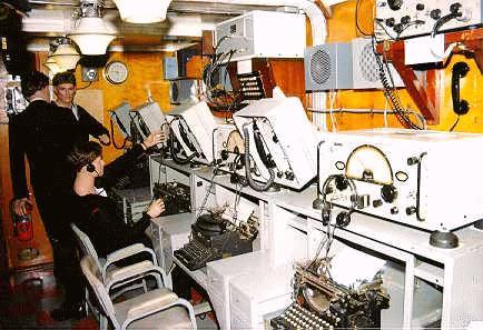 Typical layout of the main radio room |
|
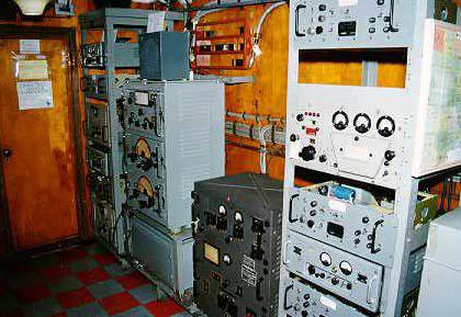
Radio 1 Starboard View This was the typical layout of the main radio room in Canadian Tribal Class destroyers during the 1950's and 1960's. At each operating position, an operator copied the 'broadcast' using a Marconi CSR5A general coverage receiver. The broadcast was sent at 25 wpm and the messages were copied on typewriters. Some of the broadcast messages were coded, so they were forwarded to the Crypto Office for further processing. |
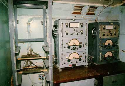 Radio 2 Before |
|
Radio 2 Before/After These port side Before/After views of Radio 2 show the fitting of the Marconi two Marconi CM11 transmitters and the three Channel Amplifier Units. Radio 2 provided additional radio circuits in the event that Radio 1 was overloaded with traffic and would also provide emergency communications in the event Radio 1 was put out of action. Not shown in the photo, is the Marconi PV500 transmitter. This was a 500 watt CW transmitter which operated in the 3 to 19 Mhz band. |
 Radio 2 After |
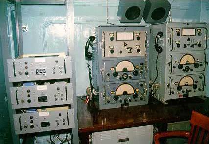
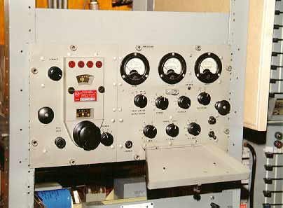
 Radio 1 Port Side View |
|
Radio 1 Port Side View Some of the ship's 200 to 400 Mhz UHF AM receivers and transmitters are mounted in the two equipment racks at the left and right side of the photo. The short unit in the middle is the TDQ transmitter. To its left, is the four piece Marconi CM11 transmitter/receiver. In the right most rack, is the RCK receiver, the unit with the three, circular, side-by-side meters. |
 Radio 3 Before |
|
Radio 3 Before/After Radio 3 was an unmanned radio room which housed four out of the seven UHF voice communications channels. The BEFORE photo shows the sad state of the room after being subjected to years of water seepage. Shortly after shooting the AFTER photo, the equipment racks were installed and the balance of the restoration was commenced. |
 Radio 3 After |
 Radio 4 Before |
|
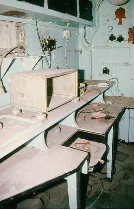
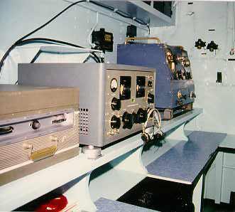
Radio 4 Before/After This was typical of an electronic warfare office on a Tribal class destroyer. The BEFORE photo depicts the appearance of the office after 30 years of deterioration. In the AFTER photo, three major pieces of equipment have been installed. At the right most side, is the Marconi FM12 MF/DF receiver, first built in the early 1940's and operated in the frequency bands of 42 khz to 1060 khz. In the middle, is a Hammarlund SP600 receiver which mainly monitored CW transmissions from Russian fishing trawlers which shadowed NATO naval exercises. The transmissions were recorded on the reel to reel tape recorder at the left of the photo. When the ship docked, the tapes were sent to Ottawa for analysis. Missing (above the SP600) is the AN/SRC501 HF transceiver. This AM only unit, operated at a 12 watt power level in the 2 to 4 Mhz band. Hidden from view, is the AN/UPD501 centimetric direction finding receiver which was used to locate radar emissions from adversary ships. |
 Radio 4 After |
 TDQ Transmitter |
|
TDQ Transmitter The TDQ, originally designed in 1943 was a 45 watt VHF AM transmitter operating in the frequency range of 115 to 156 Mhz. It could operate on one of four crystal controlled channels. Weighing in at 285 pounds, its weight to power ratio was very disproportional when compared to today's modern gear. |
 RCK Receiver |
|
RCK Receiver RCK Receiver weighing in at 117 pounds, the RCK was a low radiation, AM VHF receiver built by the E.H. Scott Radio Laboratories during the 1940's. The RCK operated in the 110 to 160 Mhz band using four crystal controlled channels. |
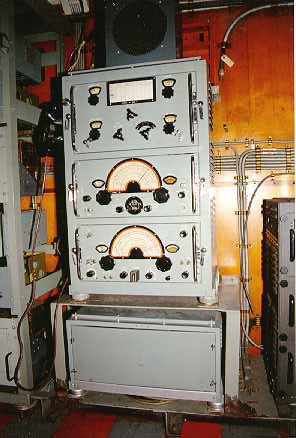 CM11 Transmitter/Receiver |
|
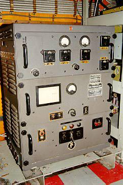
CM11 Transmitter/Receiver First built in 1942 by the Marconi company, the CM11 was a transmitter receiver capable of operating in the 375 khz to 13.8 Mhz bands with the exception of the broadcast band. It had three modes of operation: 100 watts on CW, 70 watts on MCW and 30 watts on radio telephone. From bottom to top, is the power supply, the receiver, the transmitter and the antenna tuner. At 478 pounds, it wasn't very portable! |
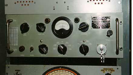
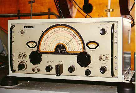 CSR5A Receiver |
|
CSR5A Receiver First built by Marconi in 1942, this general coverage receiver was capable of receiving CW or AM signals in the 80 khz to 30 Mhz bands. It was a thirteen tube receiver weighing in at 68 pounds without power supply. The most notable feature, is the four position IF band pass filter to reduce interference. |
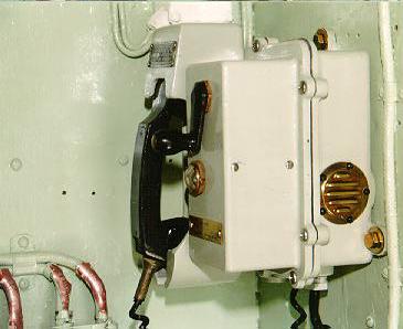
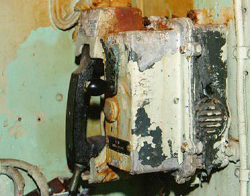 Sound Powered Telephone Before |
|
Sound Powered Telephone Before/After These were first designed by the Telephone Manufacturing Company of London England during the 1940's. A sound operated telephone does not use external power. Instead the user's own voice generates electrical power to run the device. The louder one speaks, the louder one is heard at the far end. This telephone technology could be found in many ships of many navies during the middle part of the 20th century. The BEFORE photo shows an example of the telephone as found in Radio 3. Eight hours of labour, restored the unit back to a near new condition as evidenced in the AFTER photo. |
 Sound Powered Telephone After |
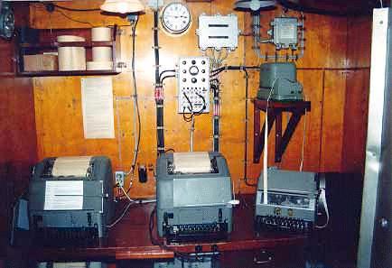 Message Centre |
|
Message Centre All messages to and from the ship passed through the Message Centre. This port side view shows some of the Teletype equipment that was fitted. At the left and centre, is the Model 15 Teletype. At the right, a Model 14 Reperforator. Above that is the Model 14 T-D (tape reader). In its heyday, this state of the art gear ran at the incredible speed of 45 baud (60 WPM)! |
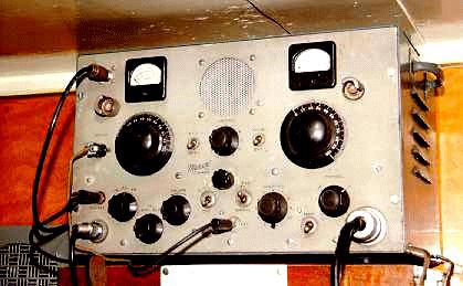
 Marconi B28 Receiver |
|
Marconi B28 Receiver This was a dual range superheterodyne receiver which was developed from the Marconi CR100/4 series of receivers of 1940. The low frequency coverage was 60 to 420 khz while medium/high frequency coverage was 500 khz to 30 mhz. The B28 receiver was fitted aboard Haida until the mid 1940's. Being of British design, the primary input power was 230VAC at 50 hertz. |
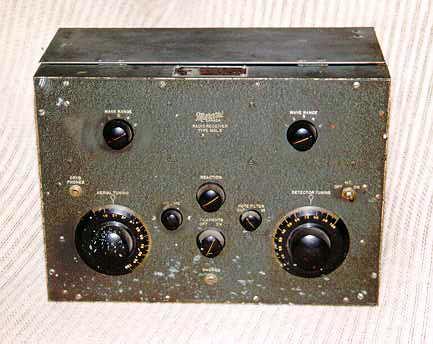 MSL5 Receiver |
|
MSL5 Receiver Made by Marconi in the early 1940's, this was a four tube, low/medium frequency regenerative receiver, operating in the 15 to 1550 or 15 to 1775 khz band depending on the variant. One unique feature in this design, was a self-contained, crystal radio in case of power failure. In normal operation, stations were tuned in by operating two separate tuning controls and two non-ganged range switches. For CW reception, a 1440 Hz note filter could be used. |
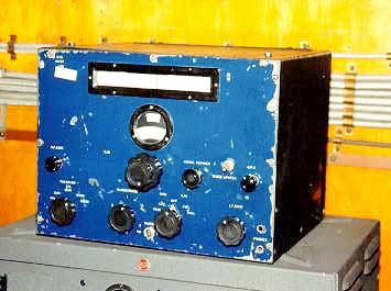
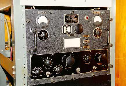
 AN/SGC1A Radio Teletype Terminal Set |
|
AN/SGC1A Radio Teletype Terminal Set This device permitted the transmission and reception of radioteletype (RATT) messages between stations that were similarity equipped. It employed 200 Hz audio frequency shift keying using 500 and 700 Hz tones to represent RATT mark and space conditions. This terminal set was first manufactured in 1950 by the Remler Co. Ltd. of San Francisco. |
 FR12 Transmitter/Receiver |
|
FR12 Transmitter/Receiver Made by Canadian Marconi in 1944, the FR12 was a three mode transmitter/receiver - CW, MCW and radio telephone. Power input was 15 watts on CW, less on MCW and even less on phone. It was capable of transmitting on low wave (375 to 580 kcs) or short wave (1700 to 4200 kcs) depending on the model type. On receive, it could tune from 300 to 4200 kcs continuously. Input power to the FR12 was 12 volts DC at 6 amps on receive and 13 amps on transmit! |
 RAK5 Receiver |
|
RAK5 Receiver Designed in the 1930's, this six tube regenerative receiver was capable of receiving signals between 15 and 600 kcs. Tuning was accomplished through the use of circular, geared logging scales for both coarse and fine tuning. On Haida, the sole purpose of this unit was to receive low frequency RATT signals and provide input to the frequency shift converter. It still receives remarkably well despite its antiquated design. The RAK5 aboard Haida (S/N 112) was built by RCA Victor in Montreal and weighs 74 pounds. It is interesting to note that this receiver was still in use by the RCN in 1962. |
 SCR522 Transmitter/Receiver |
|
SCR522 Transmitter/Receiver The SCR522 was a voice only, transmitter/receiver operating in the 100 to 156 Mcs bands with a power input of 8 to 9 watts. It was re-design of the British TR 1133 VHF set in order that it could be manufactured with American tooling. Operation was provided on any one of four crystal controlled channels. Integrally mounted in a common case, was the BC624A VHF receiver and the BC 625A VHF transmitter. Normally, the SCR522 was fitted into aircraft, however, in this instance, it was a case of the navy adopting a piece of equipment from another service for it's own use. The unit on display was an ex-RCAF unit and was reconditioned by CAE Industries in Montreal. Many of these sets were supplied by the Colonial Radio Corporation to the Allied forces in 1943. |
 Remote Control Unit (RCU) |
|
Remote Control Unit (RCU) This device allowed a radio channel to be controlled from a remote location on the ship. An RCU supported both voice and CW operation and provided the functions of an intercom. There were fourteen such units fitted aboard Haida, mainly on the bridge and Operations Room. |
 Jerry Proc, VE3FAB (left) and Jim Brewer |
|
Jerry Proc, VE3FAB (left) and Jim Brewer Radio restoration volunteers abroad HMCS Haida restore part of the ship's radio remote control system. At decommissioning, all of the cables connecting to the entire system were severed by the Navy. It took 4,000 wire splices and approximately 10 months of effort to restore the system back to a functional state. |
Visitors to this page since 18 August 2001
Back to Your Articles Index Page.
Army Radio Sales Co. Home Page.