|
Home
::
|
Radio Set SCR-193-KW
Required Parts
Items necessary for the installation of Radio Set SCR-193-KW (Water Proof) in Truck,
1/4-ton, 4 x 4, are listed below.
| Quantity | Stock No. | Item |
| 1 | 2A275-27 | Antenna A-27, phantom. |
| 1 | 2Z1108 | Box BX-8. |
| 1 | 2Z1119 | Box BX-19-( ), for receiver spare tubes. |
| 1 | 2Z1121 | Box BX-21, for Boxes BX-8, BX-19-( ), headsets, etc. |
| 1 | 2Z1848 | Case CS-48, for transmitter tuning unit. |
| 1 pt | Cement, Elastic, No. 3M, Minnesota Mining Company. | |
| 1 | 2Z2599-239 | Chest CH-239, for auxiliary tuning unit. |
| 1 | 2Z2651-421 | Clamp MC-421, for securing Mast Sections MS-49 and MS-50. |
| 1 | 2Z2651-422 | Clamp MC-422, for securing Mast Sections MS-50 and MS-51. |
| 1 | 2Z2651-423 | Clamp MC-423, for securing Mast Sections MS-51 and MS-52. |
| 1 | 2Z2651-424 | Clamp MC-424, for securing Mast Sections MS-52 MS-53. |
| 2 | 6Z3147-1 | Connector No. 61004 and Bondnut BL-50 (Appleton). |
| 8 | 6Z3147 | Connector No. 61007 and Bondnut BL-50 (Appleton). |
| 1 | 3E1270 | Cord CD-270, connects Radio Receiver BC-312-( ) to terminal Block TM-183. |
| 1 | 3E1l75 | Cord CD-175, connects Radio Transmitter BC-191-( ) to Dynamotor Unit BD-77-( ). |
| 1 | 3E1265 | Cord CD-265, for Loudspeaker LS-3. |
| 1 | 3E1999-171 | Cord CD-1171. connects Radio Transmitter BC-191-( ) to Terminal Block TM-183. |
| 1 | 3E1999-172 | Cord CD-1172. connects Radio Transmitter BC-191-( ) to Dynamotor Unit BD-77-( ). |
| 1 | 3E1999-173 | Cord CD-1173. connects Dynamotor Unit BD-77-( ) to terminal box or power take-off terminal. |
| 2 | 3E1307A-5.5 | Cord CD-370-A, 65" for Headset HS-30-( ). |
| 1 | 3E1318 | Cord CD-318-( ), for microphone. |
| 2 | 3E1604 | Cord CD-604, for connecting Headset HS-30-( ), Cord CD-307-A. |
| 3 feet | 3E2l31 | Cordage CO-131. |
| 1 | 2Z3367 | Cover BG-67-( ), for mast base. |
| 1 | 2Z3375 | Cover BG-75-( ), for receiver. |
| 1 | 2Z3378 | Cover BG-78-( ), for transmitter. |
| 1 | 3H1359 | Cover BG-79-( ), for Dynamotor. |
| 1 | 3H1777 | Dynamotor Unit BD-77-( ), including Mounting FT-107-( ) and spare parts. |
| 2 | 2B830 | Headset HS-30-( ). |
| 1 | 6L50-193KWV26 | Hardware bag. |
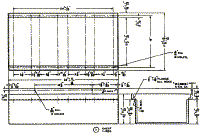
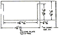
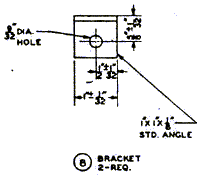
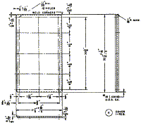
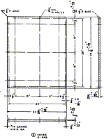
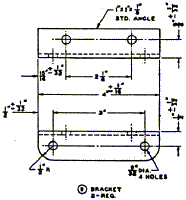
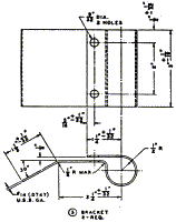
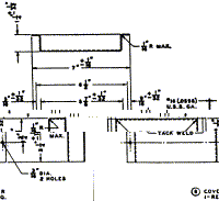
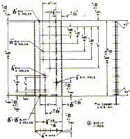
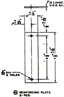
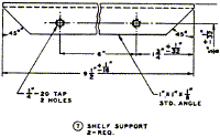
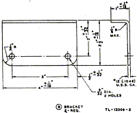
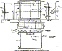
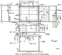
| 1 | 2Z5725-515 | Installation Kit MC-515, consisting of one right-hand cabinet (figure 15), One left-hand cabinet (figure 16), two covers (figure 19), one cover for Terminal Block TM-1 83, two brackets (figure 14), two reinforcing plates (figure 14),one shelf (figure 14), and mounting hardware. |
| 3 | 3G586 | Insulator IN-86, for tying down mast sections. |
| 2 | 3G621 | Insulator IN-121. |
| 1 | 3G598 | Insulator IN-98. |
| 1 | 3Z3445 | Key J-45. |
| 1 | 2Z6303.1 | Loudspeaker LS-3. |
| 1 | 2A2088-57 | Mast Base MP-57. |
| 1 | 2A2090-63 | Mast Bracket MP-63. |
| 1 | 2A2349 | Mast Section MS-49. |
| 1 | 2A2350 | Mast Section MS-50. |
| 1 | 2A2351 | Mast Section MS-51. |
| 1 | 2A2352 | Mast Section MS-52. |
| 1 | 2A2353 | Mast Section MS-53. |
| 2 | 2B1567 | Microphone Cover M-367. |
| 1 | 2B1617 | Microphone T-17-( ). |
| 1 | 2B1645 | Microphone T-45. |
| 1 | 2Z6712 | Mounting FT-172. |
| 1 | 2Z6718 | Mounting FT-178. |
| 1 | 2C4312 | Radio Receiver BC-312-( ), including Mounting FT-162, Dynamotor DM-21, and one set of tubes installed. |
| 1 | 2C6191 | Radio Transmitter BC-191-( ), including Mounting FT-151-( ), and one each Socket Caps M-163-( ), M-164-( ), and M-165-( ). |
| 1 | 2Z8056 | Roll BG-56-( ), for Mast sections. |
| 50 ft. | 6Z7926 | Rope RP-5. |
| 1 | 2Z8793 | Socket Cap M-163-( ). |
| 1 | 2Z9313 | Terminal Block TM-183. |
| 1 | 2C8005 | Transmitter Tuning Unit TU-5. |
| **1 | 2C8006 | Transmitter Tuning Unit TU-6. |
| 12 ft. | 1B128 | Wire W-128. |
| ** If authorised, four additional auxiliary tuning units, one each Transmitter Tuning Unit TU-7, TU-8, TU-9, and TU-10, may be installed in chest CH-239 replacing rear seat as shown in figure 19. | ||
Assembly and Installation
a.) Preliminary Check.
Radio Set SCR193-KW (waterproof) may be installed in Truck, 1/4-ton, 4 x 4, with either of
the following 12-volt conversion kits.
Check to see that the conversion has been made before beginning installation.
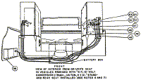
(1) Under-the-hood conversion kit in which all 6-volt electrical components of the vehicle are replaced by 12-volt components. Two 6-volt storage batteries, one originally furnished with the truck, and one supplied with the conversion kit, are installed between the front seats to furnish, in series, 12-volt power supply for both the radio set and the vehicular system.
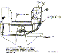
(2) Power-take-off conversion kit in which a 12-volt generator and
regulator is mounted over the transmission of the vehicle to be driven by a belt and
pulley
operated off shaft of the transmission. Two 6-volt storage batteries are supplied with the
conversion kit and
are installed, one behind each front seat. These two batteries, in series, furnish 12-volt
power for operation of the
independently of the 6-volt system of the vehicle.
b.) Procedure.
Components of the radio set should be installed as shown in figure 19, and as directed
below.
c.) Left-Hand Cabinet.
Install the items listed below inside the left-hand cabinet, details of which are shown in
figures 14, 16, and 17.
Part and Location |
Method and Materials |
| Mounting FT-107-( ). | Attach to the floor of the cabinet, left portion, with six 1/4-inch-20 x 3/4-inch screws, nuts, and lockwashers. |
| Dynamotor Unit BD-77-( ) and Cover BG-79-( ). | Place the Dynamotor unit on the mounting and secure in place with the snap-slide fasteners provided. Place the cover over the dynamotor unit. |
| Shelf (part of left-hand cabinet). | Fasten inside the cabinet with the hardware provided. |
| Mounting FT-162. | Attach to the left portion of the shelf, inside the cabinet, with ten No.10-32 x 3/4-inch screws, nuts, and lockwashers. |
| Mounting FT-178. | Attach to the rear wall of the cabinet, near the top, as shown in figure 19, with four No 10-32 x 1/2-inch screws, nuts, and lockwashers. |
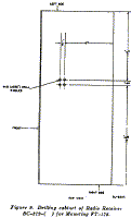
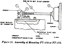
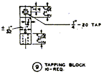
| Radio Receiver BC-312-( ) and Cover BG-75-( ). | Remove the receiver from the cabinet. Drill the top of the cabinet as shown in figure 9 and attach the small angle bracket which is supplied with Mounting FT-178. Replace the receiver in the cabinet, place on Mounting FT-162-( ) and secure with the snap-slide fasteners provided. Cut a slot in Cover BG-75-( ) to admit item 1, figure 10, and complete the assembly of the mounting as shown in figure 10. |
| Loudspeaker LS-3. | Attach to the rear wall of the cabinet, upper right portion, as shown in figure 19, with four 1/4-inch-20 x 5/8-inch screws on the back of the speaker. |
| Terminal Block TM-183 and cover. | Attach the terminal block to the right portion of the shelf inside the cabinet with the provided hardware. Fasten the cover over the terminal block after the connections are completed. |
d.) Right-Hand Cabinet.
Install the items listed below inside the right-hand cabinet, details of which are shown
in figures 14, 15, and 17.
Part and Location |
Method and Materials |
| Mounting FT-151-( ). | Attach to the floor of the cabinet as shown in figure 19, with ten 1/4-inch-20 x 3/4-inch screws, nuts, and lockwashers, placing the nuts on the inside of the cabinet. |
| Mounting FT-172. | Attach to the rear wall of the cabinet near the top centre, as shown in figure 19, with the hardware provided. |
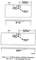
| Radio Transmitter BC-191-( ), and Cover BG-78-( ). | Drill the top of the transmitter cabinet as shown in figure 11. Place the transmitter on Mounting FT151-( ) and secure with the snap-slide fasteners provided. Cut a slot in Cover BG-78-( ) to admit item 1, figure 10, and place the cover over the transmitter. Complete the assembly of Mounting FT-178 as shown in figure 10. |
| Insulator IN-98. | Attach to the centre of the right end panel with the hardware provided. |
e.) Additional Components.
Complete the installations in the following sequence.
Part and Location |
Method and Materials |
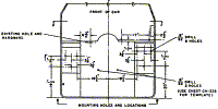
| Cabinets (left-hand and right-hand). Case CS-48. | Secure to the rear wheelwells as shown in figure 19, using the hardware
provided. Drill two holes in Case CS-48. Secure the case to the floor of the left-hand cabinet using two of the screws that secure the cabinet to the vehicle. |
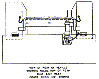
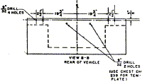
| Rear seat-back and footman's loops. | Remove the rear seat-back from the vehicle. Cut and drill the seat-back
as shown in detail C, figure19. Attach the three footman's loops to the seat-back with the hardware provided. Secure the seat-back to the brackets on the cabinet, right and left, as shown in figure 17. |
| Roll BG-56-( ). | Attach to the seat-back with the footrnan's loop and the provided strap. |
| Mast Bracket MP-63. | Secure to the spare wheel bracket at the rear of the vehicle using' the same nuts which support the spare wheel. |
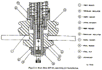
| Mast Base MP-57. | Refer to figure 8 and assemble the mast base as follows: Place item 1 over the hole in the mast bracket. Place item 2 over item 1. Place item 3 over item 2. Insert item 4 through the hole in the mast bracket. Place item 5 over the flange of item 6. Insert item 6 upward through the hole in the mast bracket. Place items 7 and 8 beneath item 6 and fasten the entire assembly in place with items 9 and 10. |
| Insulators IN-121. | Install one through the hole in the mast bracket. Install the other through the hole In the end of the right-hand cabinet (flange on the outside) with a rubber washer on each side of the cabinet wall and a large metal washer over the rubber washer on the inside of the cabinet. Use elastic cement to make a watertight joint. |
| Mast Sections MS-49 to MS-53 and Clamps MC-421 to MC-424. | Screw the mast sections together and secure with the clamps. Fasten the clamps to the male end of the mast sections. Then screw the mast antenna into the mast base. When not in use, stow the mast sections in Roll BG-56-( ). |
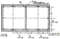
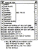
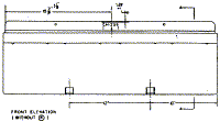
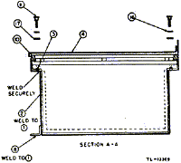
| Chest CH-239 and Tuning Units TU-7, TU-8, TU-9, and -TU-10 (when authorised). | Remove the rear seat from the vehicle and mount Chest CH-239 with the hardware provided. Figure 13 shows details and figure 18 shows assembly of the chest. Insert the tuning units into the chest and fasten the lid on the chest. |
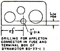
| Connectors No. 61004 and No. 61007, and Bondnut BL-50. | Install in the positions where shown in figure 19. Use elastic cement to make waterproof connections with the cabinet. |
f.) Cording and Wiring.
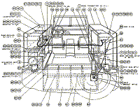
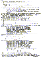
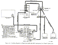
1) Cord wire Radio Set SCR-193-KW (waterproof) as shown in figures 19 and
20. Fasten all cordage in place with the provided clamps and hardware as shown in figure
19. Wrap enough friction tape around the antenna lead in wire and apply elastic cement to
make a water-tight joint were the wire passes through Insulator IN-121 in the cabinet.
Connect and secure so as not to interfere with the accessibility and operation of the
equipment. Enough slack must be left to permit free movement of all units having shock
mounting. Cording or cable likely to rub against sharp edges should be taped with at least
two layers to prevent damage. Soldertin all wire ends.
(2) To prevent accidental shorts of the battery, do not connect the positive 12-volt and negative 12-volt leads (in the terminal box) until all other connections have been completed.
Back to Installation of Radio Equipment in Truck, 1/4-Ton, 4 x 4 Index Page.
Army Radio Sales Co. Home Page.

