By Ray Robinson
VK2ILV
E-Mail robinson@srsuna.shlrc.mq.edu.au
The AR7 is a communications receiver covering LF and HF bands. It was made in Australia during 1940 and bears an extremely close resemblance to the National HRO receiver. The receiver has a tuning range from 138kcs to 25mcs, with a gap of 45kcs either side of the 455kcs IF. The internal design is a single conversion super heterodyne receiver with 2 RF stages, 2 IF stages, a BFO and an "S" meter amplifier. The sensitivity is quoted as 1 micro volt. The front panel is stainless steel and it is a very distinctive looking receiver.
It is a good performer, sensitive, has a nice feel, is easy to tune, but hard to find the correct frequency, by reading the frequency from the dial number and coil box graph. It really needs a crystal calibrator. I use it for the weekly W.I.A. (Wireless Institute of Australia) broadcast, so it gets turned on once a week, and is so stable, than I don't have to retune. It is very clear for AM but a bit fiddley for SSB.
The controls are: RF gain, BFO note, AVC/BFO switch, Adjust "S"meter, Tone, Tuning, Noise limiter, Selectivity, Crystal IN/OUT switch, Crystal Phasing, Audio gain. The Audio gain control has an OFF position which removes the HT so that the coil boxes can be changed.
It has two 6U7G RF stages, a 6K8 G mixer, two 6U7G IF stages at 455kcs, a 6G8 G detector/AVC/audio preamplifier, and a 6V6 G audio output amplifier. It has a 6C8G twin triode as a BFO and "S" meter amplifier. It also has a crystal filter. The IF alignment should be done very carefully, as any misalignment will reduce the effectiveness of the filter. It is best done with a sweep generator. The valve heaters are connected in series, for 12 volt operation. Here is the circuit and parts schedule, supplied by PM.
 AR-7 Radio Receiver |
|
The external power supply and speaker, are usually mounted in a short
19" rack, the AR7 at the bottom, the speaker in the middle, and the power supply at
the top. The complete unit weighs about 118 pounds. The power supply was switchable
between 12v and 240v. The transformer has 2 primary windings, one for the 240v mains, and
another for the 12v vibrator. It has two 6X5GT rectifiers , each with their plates tied
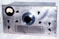
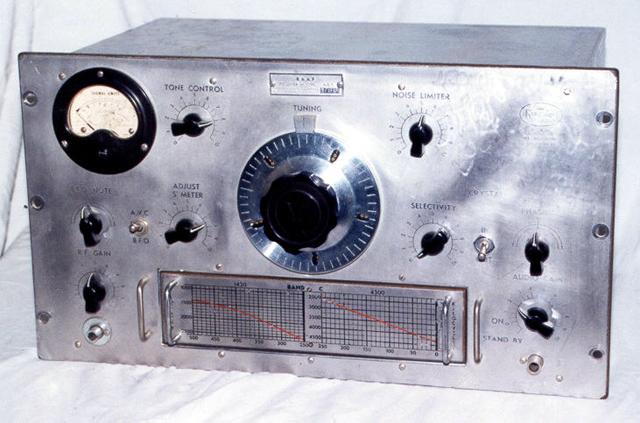
together to serve as individual single diodes. I don't have an original power supply. The receiver was used as a fixed frequency monitoring receiver for aircraft. It was extremely stable. The model shown has an R.A.A.F. nameplate, and serial number 1786. The manual I have is a D.C.A. (Department of Civil Aviation) version and is a 1947 issue. This is a front view of the AR7 with the band C coil box plugged in. The left hand phone jack has had the hole filed out to take a pilot light. I have fitted the original phone jack, but have has to use a washer to cover the hole. Other than that, the front is completely original. It has 5 plug in coil boxes. The coil boxes were: band A 140-405kcs, band B 490-1430kcs, band C 1.420-4.3mcs, band D 4.25-12.5mcs, band E 12.5-25mcs. The Army version had an extra coil box covering 50-150kcs. The large dial is a 20:1 reduction drive and has graduations from 0 to 500. It acts like a flywheel when tuning across the band, and has an effective scale length of 12 feet. |
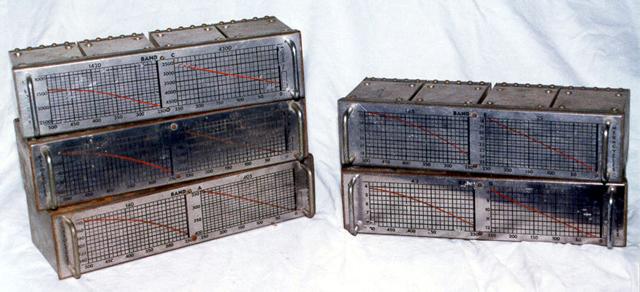 AR-7 Receiver, Plug in Coils |
The dial shaft goes into a right angle reduction gearbox and has 2 output shafts that drive 2 dual gang capacitors. The arch of the gearbox and the 2 capacitors are visible in the photograph. The graph on the front of each coil box is used to covert the dial reading to frequency. The DCA had a modification where the oscillator coil was removed from the coil box and a crystal was mounted in there. This crystal locked the receiver to one frequency.
 AR-7 Receiver Internal View |
|
This is a rear view of the AR7 with the case removed. The chassis is made of 18 gauge sheet steel, copper, and cadmium plated, and spot welded. It is heavy. The left side 4 pin male plug is the power input. The right side 5 pin socket is the speaker output. The speaker transformer shown is incorrect. It was a big square block, which also had a 600 ohm output for driving a line. Please call me if you have one in your junk box. The aerial could be a single wire or a balanced doublet, as there are 3 terminals on the back. These are plastic on this example, and I would like to change them to the original ones, if I knew what they were. The photograph has a slight discoloration, probably due to light getting into the camera. I will have to re-photograph the inside. |
I have had this AR7 since I was 14 years old. It was my first communications receiver. I used to have a rack, speaker, and power supply for it, but they have disappeared, over the years due to moving house. I had to do extensive work to restore it to original condition, or as near as I could get it. The case has been repainted grey. The valve heaters had to be rewired from 6v to the original 12v, and all non original plastic wire, replaced with cotton covered wire. I had to find the original phone jacks, to replace a modern jack and a dial light. I made a cover for the crystal filter and rewired inside the crystal filter box. I replaced the RF gain, Selectivity, and AF gain control potentiometers as they were faulty. The valves had been replaced with metal valves so I returned these to the correct G types. I had to make bases for the valve shields, as these had been removed for the larger based metal valves. I then had to find the correct valve shields. The capacitors were mostly out of tolerance or leaky, so I replaced them all. I found 2 bad resistors and replaced those with the correct Body/Tip/Dot type, not modern colour coded striped resistors. There was a silicon rectifier under the space where the speaker transformer should be, and a mains power transformer. These were removed and a speaker transformer put there. I am still looking for the correct type. A new ceramic speaker 5 pin socket was fitted. The crystal was missing so a new one was fitted. I then did a complete alignment, and had a lot of trouble trying to get the crystal filter working properly. When I finally used a sweep generator, the alignment took 5 minutes, and was extremely accurate. This refurbishment took over 6 months.
Howard Kingsley Love started the Kingsley Radio company in Melbourne, Victoria, in 1931. They manufactured domestic radios, and special orders, including diathermy machines. The R.A.A.F (Royal Australian Air Force) produced a specification for an Australian made high performance communications receiver. The Kingsley Radio company designed a receiver called the K/CR/11 and submitted it. It was adopted as the AR7. They placed an initial order for 20 receivers. The Army also adopted this receiver as the Reception Set No.1 and it had an engraved brass panel with a black background. I've seen AR7s with green panels. Another version was made for the Dutch Navy with a front panel in Dutch. There were more than 3200 receivers made.
References
"When I think Back", Neville Williams, Electronics Australia, July/August 1994.
"The Kingsley K/CR/11, (AR7)", Warick Woods, H.R.S.A. (Historical Radio Society
of Australia) Radio Waves, October 1997.
"Airways Radio Equipment Receiver Type A.R.7", Directorate of Airways,
Department of Civil Aviation, Melbourne, January 1947.
Military Radio Collection,
AR7, Dave Prince
Visitors to this page since 20 February 2000
Back to Your Articles Index Page.
Army Radio Sales Co. Home Page.