By Ray Robinson
VK2ILV
E-Mail robinson@srsuna.shlrc.mq.edu.au
The AR88 is a general purpose communications receiver manufactured by RCA in the U.S.A between 1941 and 1945. They were made in large numbers for service use. Most were sent to the U.K. and Russia for the war effort. They came in 2 versions, the AR88D and the AR88LF (low frequency version). The R.A.F. designation was R1556A and R1556B for the LF version.
They evolved into the CR88 in 1946 with crystal phasing, and the CR88A with an S meter. Later models CR91 and CR91A have the same coverage as the AR88LF. Model SC-88 is like the CR88 but shows only the band in use. CR88B is the last version in 1951 and has a crystal calibrator. D89 is a triple diversity version.
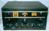
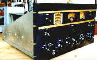
This is the LF receiver, and it is very nice to use, with the exception of the small dial scale and band indication. The tuning is smooth and it is very sensitive. It is also very stable. The front panel layout is handsome, with dial light behind the 3 windows.
The main differences between the AR88D and the AR88LF are the frequency coverage. They also have different IF frequencies (AR88D is 455kcs, AR88LF is 735kcs) and different audio output valves (AR88D is 6K6, AR88LF is 6V6).
| Tuning Bands | AR-88LF Frequency Coverage | AR-88D Frequency Coverage |
| Band 1 | 73 - 205 Khz | 535 - 1600 Khz |
| Band 2 | 195 - 550 Khz | 1.57 - 4.55 Mhz |
| Band 3 | 1.48 - 4.4 Mhz | 4.45 - 12.15 Mhz |
| Band 4 | 4.25 - 12.15 Mhz | 11.9 -16.6 Mhz |
| Band 5 | 11.9 - 19.5 Mhz | 16.1 -22.7 Mhz |
| Band 6 | 19.0 - 30.5 Mhz | 22.0 -32.0 Mhz |
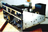
It is a 19" rack mount type chassis, and usually comes in a cabinet, the total weighing 100 pounds. It will run on 115v or 240v AC mains, 25-60 cycles and draws 100 watts. It can also run on 6v DC (12 amps) with the external power supply type MI-22215 (a vibrator supply). It can also have an external metal speaker box. The sensitivity is quoted as 15 micro volts for 20db signal to noise for MCW and 5 micro volts for CW. It will deliver 2.5 watts to the loudspeaker. The designers have put a lot of effort into screening the RF and oscillator circuits to reduce radiation, and making the receiver stable by rugged metal work, temperature compensated oscillator circuits, and a regulated HT supply for the oscillator.
Controls
There is an ANT. tuning control on the front panel to adjust the aerial. The TUNING knob
has a nice feel, and has a flywheel so you can spin it to move across the band. It has a
dial lock. There is a logging scale visible in the centre window. The left hand window has
the main tuning scale. I find this too small, and I have difficulty determining which band
I am on by looking at the numbers down the sides on the scale, as the arc is rather great.
The RANGE switch refers to the numbers 1 to 6 rather than the frequency coverage. It
switches ranges easily, but there is no indicator (either a pointer or a light) to
indicate the band. The local oscillator has a regulated supply which works well, as I can
tune to a frequency, turn the receiver off, and then come back the next day, it will still
be on frequency, with little drift during warm-up. The manual makes a special mention of
stability despite power line fluctuations. There is a wave trap in the RF stage to prevent
any signal at the IF frequency coming through. There are double IF transformers either
side of the second IF amplifier. It also has a crystal filter, which together with the
double IF transformers, changes the bandwidth to 550 cps, 2000 cps, 4000 cps, 8000 cps,
and 16000 cps, using the SELECTIVITY switch. The BFO has a control to vary the beat
note.
The noise limiter is controlled by a switch that can also turn the AVC off. There is a main switch to turn the receiver ON, and it also has positions to turn the BFO on and to mute the receiver in TRANS position. This model is fitted with an S meter to indicate signal strength. Some model just had a the model number in the window. The S meter is not very useful as it is not very sensitive to signal strength, it is more sensitive to the RF gain control position.
References
Instructions, GENERAL PURPOSE COMMUNICATIONS RECEIVER, Model AR-88.LF, RCA Victor Company,
Limited, Montreal, Canada.
Getting the Most From Your AR88, Servicing, Adjustment and Maintenance, D.M.Gill (4S7MG),
The Short Wave Magazine, August 1958, P288-297.
Getting the Utmost from the AR88, Calibration, IF and RF Alignment, Sensitivity, Checks
and General Testing, W.K.Miller (G6QF), The Short Wave Magazine, April 1953, P79-84.
Short-wave Receivers Past & Present, 3rd Edition, Fred Osterman, March 1998, P341.
RCA AR-88 -- A Classic in Radio Design, ELECTRIC RADIO, Number 15, July 1990, P12-15, P32.
Photographs courtesy of PW.
Visitors to this page since 20 February 2000
Back to Your Articles Index Page.
Army Radio Sales Co. Home Page.


