By Ray Robinson
VK2ILV
E-Mail robinson@srsuna.shlrc.mq.edu.au
The AR8 receiver is a communications receiver made by AWA (Amalgamated Wireless Australia) during World War 2 for use in aircraft. They were used in locally made aircraft like the Wirraway and imported aircraft like the Hudson. The AR8 is part of a set that consists of the AR8 receiver, the AT5 transmitter, and an Aerial Coupling Unit. All units are in the shape of a cube and can sit on top of each other. These are connected to a Junction Box and a power supply. There are 2 power supplies for this radio set. A Dynamotor set for 12 or 28 volt DC use, and a mains powered unit for 240 volt use.
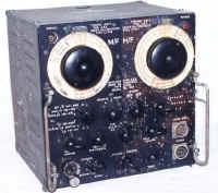
The receiver is a unique design as it has 2 RF front ends, and a common IF and Audio section. The RF sections are an LF unit and a HF unit and have independent controls, making it easy to switch between 2 stations. There is a red pilot lamp on the top right hand front panel, to indicate the receiver is on, and a dial light behind each scale, which is turned on for the appropriate RF section, indicating which section is in use. The valve heaters and pilot lamps are arranged in a series/parallel fashion to enable either 12 volt or 24 volt operation. The receiver weighs 31 pounds. It has a sensitivity of better than 3 micro volts below 9.5 mcs and better than 10 micro volts above 9.5 mcs. The frequency coverage is 140-740 KC's and 0.765-20 mcs.
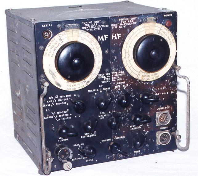 AR-8 Receiver |
The front panel is split down the middle, and it is quite common for each side to be a
different colour. Sometimes they are black, sometimes brown, and sometimes the wear around
the knobs gives a varied shade of brown. The colour difference could be due to several
reasons, being painted at different times with different batches of paint, replaced RF
units or panels, or different grades of aluminium used to make the panels. The acid in the
operators skin may have contributed to the colour change. The one pictured has a black
Left panel with a patchy brown Right panel with white corrosion spots. The side panels are
in grey crackle paint. The internal chassis is plated. The audio/IF section is independent of the RF sections. There is a 6J7G audio output valve, which is for driving headphones through an output transformer, but is insufficient for loudspeaker levels. There is a 6G8G audio preamplifier, detector and AGC valve. |
This valve has a microphone transformer in its plate circuit, so that the output valve can be used as an intercom for the aircraft crew. It is a fixed volume and works continuously, and when the receiver volume is turned up, the two are combined so that the crew can also hear the radio traffic. The next 2 valves are IF amplifiers using 6U7G valves. There is also 2 cascaded IF transformers between the IF amplifiers. There is a 6A8G as the BFO oscillator. It is very stable, allowing good SSB reception. The IF is 755 KC's which is in the broadcast band, so that the set requires all its valve shields and covers in place to avoid interference. The controls are located on the front panel by long shafts and consequently make access to the underside of the RF modules difficult. The AF/IF/BFO unit controls are: Volume control, Tone control, RT/CW switch, and Beat Note Tuning. The Volume control is unusual in that the knob turns 2 potentiometers, connected together by a chain drive. One is used for volume in the RT position and the other is used for RF gain in the CW position. Only one is active at any one time, depending on the RT/CW switch. The Tone control has a switch on the back that is used to switch the receiver On, for netting or Inter-tuning (i.e. making sure that the receiver and transmitter are on the same frequency). Normally the receiver is Off when the transmitter is On, which is controlled by a relay in the Aerial Coupling Unit. This control can override this.
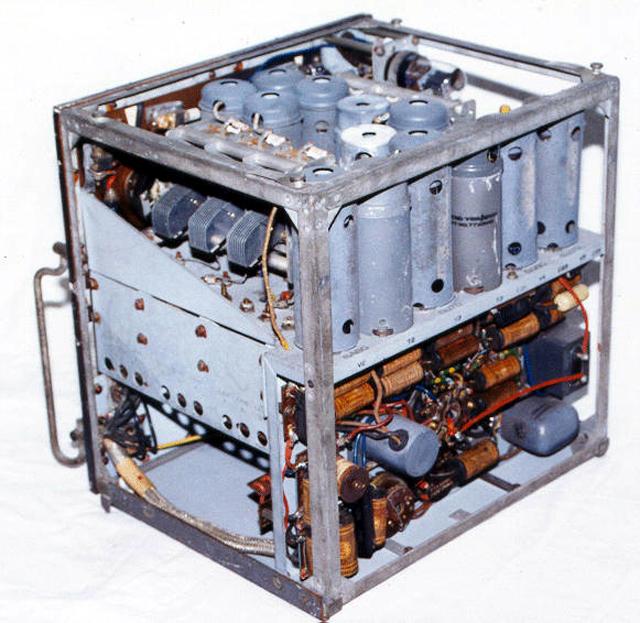 AR-8 Receiver Internal View |
There are 2 connectors on the front panel of a military Multi pin type rugged plugs.
These are often missing on receivers. The top one is for audio, keying and microphone. The
bottom one is for the power supply. The left hand side contains the LF section which is completely independent and can be removed and replaced. The front panel is split vertically to allow this. It has a large vernier tuning knob. It has a band switch which covers the ranges: band A 136-340 KC's, band B 300-740 KC's, band C 765-2050 KC's. It uses a 6U7G for the RF amplifier and a 6A8G for the mixer/oscillator. The aerial socket is in the top left hand corner. Behind the socket is a 6X5GT power rectifier valve which is used to protect the receiver if the transmitter is accidentally connected and turned on. There is a tuning control for the MF bands in the form of an aerial trimmer. |
The LF section has D/F capability and has several controls for this and a separate loop input socket. The loop connectors are difficult to find. There is a function switch which has 3 positions, one being for normal Traffic reception, the second for D/F operation, and the third for D/F Sensing of the correct bearing. In this position both of the aircraft's loop aerial and normal aerial are used and a Bearing/Reciprocal switch changes the phase to allow Sense determination. This is important in direction finding, to ensure the aircraft is flying towards the home base rather than directly away from it. There is a Sense Resistance control to adjust the aerial level. The Band switch has duplicated the band positions, as it switches in a centre tapped coil for D/F use. There is an earth lug on the bottom left hand corner.
The right side of the receiver contains the HF section which is completely independent and can be removed and replaced. It has no D/F controls. It has a large vernier tuning knob. It has a band switch which covers the ranges: band D 2-4.5 mcs, band E 4.2-9.7 mcs, band F 9-20.7 mcs. It has a 6U7G RF amplifier and a 6A8G mixer with a 6J5GT oscillator.
There is a remote control unit for the receiver, that allows remote operation of the HF tuning and the Volume control. This is achieved by 2 Bowden cables, connected between the remote control box and the receiver. The 2 knobs have to be removed and a right angle drive gearbox fitted over the each of the shafts.
The receiver (serial number 3159) was acquired for $40 at the Wireless Institute of Australia Trash and Treasure sale. I had to rewire the D/F loop socket, as it had been wired as the speaker output socket, and a speaker was screwed to the top of the front panel. I changed the power and junction box connectors back to the original type. I rewired the valve heaters back to the series/parallel arrangement, as this is a common modification to wire them as 6 volts. There were several valve shields and covers missing that I eventually managed to locate. The AR8 has black encapsulated capacitors. I decided not to replace them, and so keep the insides looking original. One coupling capacitor was leaky, so I changed that one, but hid it underneath the faulty one. It needed a complete realignment and all was well, except for a minor tracking error on the 2-4.5 mcs band that I was unable to correct.
Power Supply Type 'S'
The Power Supply Unit Type S is a 240 volt unit and has two 866 mercury vapour
rectifiers for the transmitter, that light up a beautiful blue when the transmitter is
keyed, and change brilliance as you speak. It has a thermal time delay switch that
waits 30 seconds till the rectifiers are warm and the mercury vaporised, before the HT is
applied. The manual cautions that after extended periods of non use or with new
valves, remove the HT top cap connections to the 866 rectifiers, and allow the heaters to
run for 2 minutes, to ensure all mercury is vaporised. This will prevent arcing. There is
a metal rectifier that supplies 12 volts DC for the valve heaters. It is a heavy unit
weighing 108 pounds, with perforated metal covers and a small front panel with connectors,
fuses, and Bakelite type light switches on the front. Both this unit and the DC unit
have similar control panel layouts. I don't have one of these units, so I can't supply a
photograph.
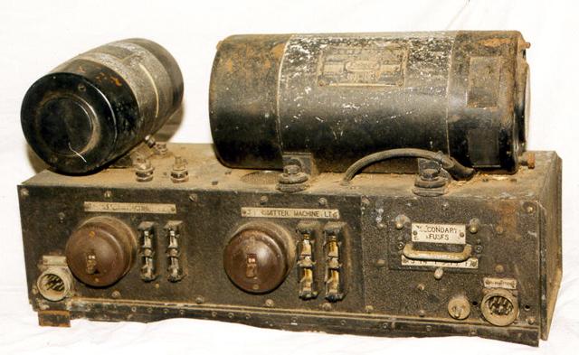 Power Supply Type 'G' |
Power Supply Type 'G' The alternative to the 240 VAC unit is a Power Supply Unit Type G and Type L which is a DC generator/motor unit, which has 2 generator/motors, a small one for the receiver, and a large one for the transmitter. They have gone to some trouble to filter out any motor noise from the supplied power. I managed to find one of these units recently at the Wireless Institute of Australia Trash and Treasure sale for $10, but have not restored it yet. Actually, one of my friends had spotted it first, and was buying it when I arrived, but he was generous enough to let me have it. Thanks Alex. The unit is heavy, and missing its back covers, and fuse holders. The insides look to be in good condition . |
References
Military Radio Collection, AR8,
Dave Prince
Military Radios, AR8, Steve Hill
Visitors to this page since 20 February 2000
Back to Your Articles Index Page.
Army Radio Sales Co. Home Page.