By Ray Robinson
VK2ILV
E-Mail robinson@srsuna.shlrc.mq.edu.au
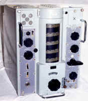
The B-40 is a communications receiver covering the HF bands. It was made in the United Kingdom by Murphy Radio and comes in 4 models. The frequency range is continuous from 600 kcs to 30 mcs. The IF is at 500 kcs and has a crystal filter. It is a single conversion super heterodyne receiver with 2 RF stages and 3 IF stages. It has a distinct looking front panel with a vertical frequency display, each band being illuminated in turn as you change bands. Some people call it the "lighthouse" style dial. The band switch is a large knob like a wing nut, as it is used to turn the the band change turret inside. It has a built in tiny speaker. The tuning knob has a flywheel, so you can spin along the dial. It weighs 114 pounds. It will work on 115 or 240 volts. The sensitivity is claimed to be 2 uv on CW for a 20 dB S/N but it seems better than this.
It was designed for the Royal Navy, and as such, had to be strong and reliable, sensitive and easy to use. It was literally built like (for) a battleship, and had to stay on frequency, when the ship fired it's guns! Consequently weight was not a factor in it's design. It was used by many navies in the world, including the Royal Australian Navy. The manual I have is dated 1956.
Performance
It is an excellent performer, very sensitive, has a nice feel, is easy to tune, and easy
to find the correct frequency, by reading the linear scale. It has a crystal calibrator to
check the dial graduations. I use it for listening to the weekly AM net, so it gets
turned on once a week, and is so stable, than I don't have to retune. It is very clear for
AM and pretty good for SSB even though there is no BFO tuning control.
 B-40 Radio Receiver |
Controls At the top on the left hand side is the speaker. Under this are the AGC ON/OFF switch and the NOISE LIMITER ON/OFF switch. Between them is the LIMITER control which can be adjusted to clip any peaks which are greater than the desired signal. Under this is the BANDWIDTH control, which has 3 positions of 8 kcs, 3 kcs and 1 kc which is a crystal filter. The B-40A has a 200 cps filter instead of a crystal filter. Below this is the SYSTEM switch. The first position switches in a CAL oscillator so that the scale can be set accurately. The top of the dial column can be opened and the scale set by moving the pointer. The next position is the R/T position, which is used for normal voice signals. |
The next is TUNE used to accurately tune in a station by listening to the heterodyne. The next 2 positions are called HIGH and LOW which have a different beat note for CW. I can tune SSB easier in the LOW position. Next to this switch is a small knob for the AF gain. Below the SYSTEM switch is an LS ON/OFF switch to silence the speaker for phones or external line connection. There is also an on/off switch on the back of the receiver to terminate the line in 600 ohms when it is not in use. The bottom switch is MAINS ON/OFF switch with the mains plug below that.
In the centre at the top is a door that opens to reveal the dial pointer adjustment. The column has a different scale for each band, and each has a light behind it to show the band in use. The band scale is very clear and easy to use. It has little dots on some of the graduations, that match the crystal calibrator. At the bottom is a small arc shaped window with a logging scale, and below this is the main tuning knob. It is large, with a flywheel and smooth to tune. It has a lock lever next to it. At the bottom is the name plate.
At the top of the right hand side is a little door, and behind this is a light and a crystal socket. If you want to crystal lock the receiver to a fixed frequency, you can plug in a crystal of the desired receive frequency (less 500 kcs). Then use the knob below this labelled CRYSTAL OFF/ON. It selects this crystal instead of the oscillator coil and turns on the light behind the door. You can then tune the receiver to that frequency, and the receiver is now crystal locked. The control below this is the ANTI-CROSS MOD. control which changes the grid bias of the first RF amplifier. This changes the working characteristics of the amplifier to reduce cross modulation from any strong adjacent signal. Normally the control is fully clockwise. The next knob is a large bar type used to change bands. The bands are; Band 1: 0.64-1.65mcs, Band 2: 1.57-4.1mcs, Band 3: 3.9-10mcs, Band 4: 9.5-18.5mcs, Band 5: 17.6-30.5mcs. A small window shows the band in use, as well as the lights behind the scale. The bottom knob is labelled GAIN and controls the RF gain. Below this are 2 jacks for headphones.
On the back are several switches and sockets. There is an audio output plug and line terminating switch, IF sockets and an aerial socket.
 B-40 Radio Receiver Internal View |
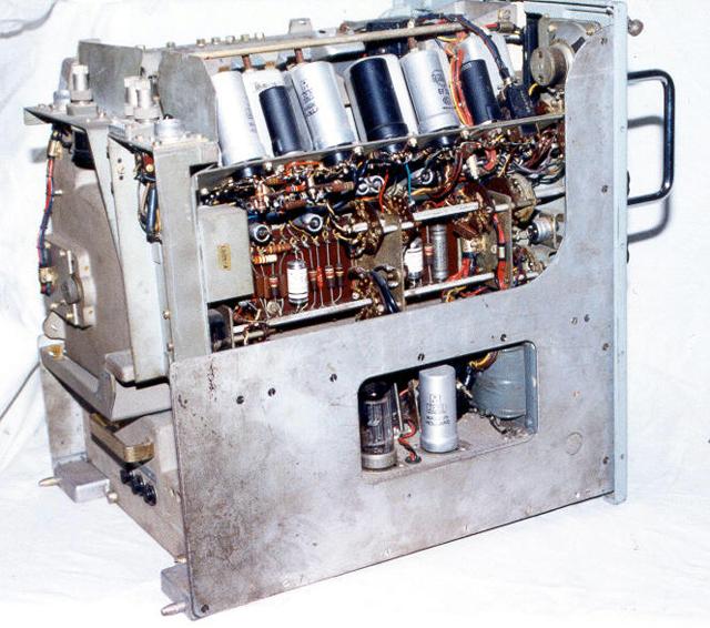
Design The first and second RF amplifiers use a CV327 and a CV303, which feed a CV302 mixer and CV327 oscillator. The IF amplifiers use three CV303 valves and the AGC and detector use a CV140 valve. The noise limiter also uses a CV140. The BFO is a CV303. The AF amplifiers are a CV303 and a CV304 with a CV346 rectifier and a CV287 regulator, for the oscillator power supply. The mechanical design is very robust. It has a cast aluminium chassis for the power supply and audio amplifier. It can be removed easily. Unscrew 2 screws at the back, remove the Volume control knob, unplug 2 Multi-pin plugs, and pull it out by the handle (visible in the photograph at the lower back, just above the fuses, the 2 screws are below the fuses). |
The U shaped cast chassis has all the heavy transformers and chokes on it. The valves in the audio section and the interconnecting plugs can be reached through a hole in the LHS of the receiver (visible in the photograph).
Above the audio section is the IF strip, which is angled so that the undersides of the valves can be accessed (also visible in the photograph at the LHS top) and at the front is the small speaker. The valves on this model are mainly the Octal type. In the centre at the top is the tuning capacitor, and on the RHS top is the RF strip, also angled for access to the underside of the valves.
Beneath the centrally located tuning capacitor and toward the right hand side, is the large band change turret (the back can be seen in the photograph). It rotates by use of the band switch knob, and positions a new set of coils for each band. The coils are mounted on cast alloy bases and are individually removable.
The case is removed by unscrewing the 2 screws at the front top, and pulling the case back. There is a rail fitted inside above the IF transformers to prevent the case from damaging the tops of the IF transformers. The B-40A that I worked on, did not have this rail, and consequently one of the IF transformers had a broken slug.
The B-40 receivers have two different types of connectors fitted to them. This one has the Plessey Mark 4 type of connectors. The mains connector is only a 2 pin socket, and the mating plug is often hard to find. I found a cache in Adelaide after searching for 2 years. I never unplug the B-40 while it has mains on it.
Different Models
There are 4 models in the B-40 series, the B-40A, B-40B, B-40C and B-40D, or more
correctly they are all "RECEIVER B-40" and "PATTERN 57140/A",
"PATTERN 57140B/C", "PATTERN 57140 D". The B-40A is easy to
recognise, as it has a cast front panel with the lettering moulded in. The B-40B, B-40C
and B-40D have plastic panels fitted over the front and they have the engraved lettering
on them. The B-40D has an extra little knob halfway up on the RHS for trimming the crystal
oscillator (when used). The other way to determine the model, is to read the nameplate!
There are 2 very similar receivers that look almost identical, and they are the same design but have a different frequency coverage. The B41 covers LF frequencies. The other model is called the 62B and is a general coverage LF and HF version. Both these are not as common as the B-40.
Restoration
I restored two B-40 receivers at the same time, so the details are a bit confused. This
one is a B-40C and the other was a B-40A.
The A model had a gold painted front panel, which required a lot of work to strip back and repaint to the original colour. They both needed an IF alignment, and the A model had no lateral bar, which meant that when the case was removed it had struck the IF cans (at some time in its life) and broken the top slug. I found that this IF can would not tune, and upon opening found the slug sitting at the bottom and not connected to the tuning screw. A new adjuster and some glue fixed that. This one had no audio, which turned out to be an open circuit resistor in the screen of the power amplifier.
Both had modified power cables. I fitted the correct 2 pin mains connector to this one, and ensured the earth was connected to the metal plug, and resolved never to unplug it while power was on. It uses a 2 pin Plessey Mark 4 connector. A 3 pin connector would be safer. The A model had a pilot light where the connector should be, so I removed this and routed the mains cable through here, rather than out through a hole in the back of the case.
The switches were a bit cracklely, due to their open design, but some cleaning fixed that. The paint on the central tuning drum had flaked off, and was in a pile in the bottom. Access was a problem, until I joined a small piece of tubing to the vacuum cleaner and sucked the flaking paint out. Most of the dial lights needed replacing.
The oscillator was not working which was tracked down to an open circuit resistor. An RF alignment was done, which brought up the sensitivity. While setting the tracking at the band ends, I accidentally received WWV on 10 Mhz. This was on a 1 meter long piece of wire from the receiver to the signal generator. The sensitivity impressed me!
Conclusion
The B-40 is a nice looking, easy to use, sensitive communications receiver. It is easy to
work on, uses readily available parts, apart from some valves and the connectors. It is a
nice receiver to own, providing you have a strong enough table.
References
Handbook for A.P.57140 Series, Receiver B-40, 1 August 1956.
Thanks to Ian O'Toole and John Wright.
Visitors to this page since 20 February 2000
Back to Your Articles Index Page.
Army Radio Sales Co. Home Page.