12 - Safety Markings.
a) Vehicles used for the quantity transportation of gasoline, fuel oil,or other flammable liquids will be marked on both sides and rear with the word"Flammable" in 6 inch letters, and the words "No Smoking Within 50Feet" in 3 inch letters and numerals. The marking will be placed in two lines, withthe word "Flammable" on the top line. The marking will be applied in the samecolour as the vehicle registration marking.
b) Vehicles carrying explosives or other dangerous materiel will bemarked as follows:
(1) When used for the transportation of such dangerous materiel overpublic highways, vehicles will be marked or equipped with appropriate placards inaccordance with AR 55-355.
(2) When used for the transportation of such dangerous materiel totraining areas, vehicles will be marked or equipped with placards on both sides and ends.The words "Explosives" will be marked in white letters not less than 3 incheshigh on a red background in accordance with AR 385-63. Reflectorized markers should beused when available,
c) When authorised by the responsible commander, stripes of acontrasting colour may be applied to certain vehicles and equipment used in a non-tacticalarea, which, because of size, construction, or function, present a possible hazard. Thesestripes are applied to permit vehicles to be more readily seen by drivers of othervehicles. They are normally applied to the rear of such vehicles; they may, however, bealso applied to the front or certain side surfaces if required.
(1) The stripes will be applied across the face of the bumper, oracross the width of the vehicle on a flat surface above the bumper in a band not to exceedtwo feet in height. Other appropriate surfaces may be used when necessary.
(2) Width of the stripes will be four inches with a four inch spacebetween stripes. They will be inclined at a 45' angle in opposite directions from thecentreline of the vehicle, to form an inverted V pattern.
(3) Gloss yellow, Colour Chip No. 13538, will be used for stripes onvehicles painted olive drab or other dark colour.
(4) Gloss black, Colour. Chip No. 17038, will be used for stripes onvehicles painted yellow or other light colour.
d) DA Label 76 (A Good Driver) for promoting safe driving practices,may be requisitioned through normal publications supply channels, and will be applied toall motor vehicles as follows:
(1) Truck, utility, 1/4, T, M38 -- Directly under the left windshieldwiper motor.
(2) Truck, utility, 1/4, T, M38Al -- Centre of the map compartment door.
(3) Truck, utility, 1/4, T, M151 -- Windshield frame, below the glass andto the left of the steering column.
(4) Trucks, 3/4, T, and over -- Upper and forward end of the left frontinside door panel.
(5) Tanks, self propelled artillery, personnel and cargo carriers,highspeed and cargo tractors, and tank recovery vehicles Left bulk head at operators eyelevel.
e) All motorised materials handling equipment will be marked with thelegends "No Smoking" and "No riders."
(1) These legends will be placed on a surface facing the operator.
(2) The markings will be applied in 1 inch letters of the same colour asthe registration markings.
(3) The markings may be applied horizontally to read left to right orvertically to read top to bottom.
13 - Technical Markings.
a) Tire Pressure. The prescribed vehicle tire pressure will be marked onthe dash of all motor vehicles and pneumatic tired equipment. This marking will also beapplied to the fenders above each wheel or, if fenders are not used, to the body or frameimmediately above each wheel. On towed vehicles or equipment, this marking will be appliedto the body or frame immediately above each wheel. On tandem axle vehicles the markingwill be centred between the two wheel sets.
(1) The markings will consist of the numerals representing the properpressures, preceded by the letters TP.
(2) Letters and numerals will be 1 inch high and in the same colour asthe registration marking.
b) Maximum Speed. When maximum speed is specified by a manufacturer,or in an applicable technical manual, and when appropriate operation plates are notavailable, the maximum speed of the vehicle in its highest range and gear ratio will bemarked on the dash.
(1) The marking will consist of the numerals representing maximumspeed, preceded by the abbreviation "Max Speed".
(2) Letters and numerals will be 1 inch high and in the same colour asthe registration markings.
c) Arctic Lubricated. All vehicles and equipment processed withspecial arctic lubricants and/or other materials for operation in cold climates will bemarked with a temporary marking as follows:
(1) The words "Arctic Lubricated" will be marked in thefollowing order of preference:
(a) Adjacent to the agency identification or registration marking oneach side of the vehicle or equipment.
(b) Adjacent to the name or identification plate.
(c) On another conspicuous location in order that the markings may bereadily seen prior to operation or use. Specific locations may be prescribed in applicabletechnical publications for the vehicle or equipment.
(2) Letters of the marking will be 1 inch high and in the same colouras the registration marking.
(3) The marking will be kept in a legible condition until the vehicle orequipment is de-processed, and will then be thoroughly removed.
d) Engine Hood Safety Hook. All tactical use wheeled vehicles whichare equipped with an engine hood safety hook will be marked with the words "Warning:Secure Hood in Raised Position with Safety Hook Before Servicing Engine".
(1) The marking will be applied at the rear area on the underside of thehood panel.
(2) Letters of the marking will be 1 inch high, and white.
e) Crane Boom. Boom extension markings are required to assure operationwithin boom radii limits specified on the crane safe load data plates.
(1) Boom markings will be applied in the permanent method of marking.Colour will be the same as the registration markings.
(2) Procedure for Trucks M60 and M108.
(a) Retract boom and retain in horizontal position.
(b) Measure, scribe, and mark a 3/1 inch vertical stripe along the outeredge of the shipper, extending the stripe onto the boom (figure 10).
|
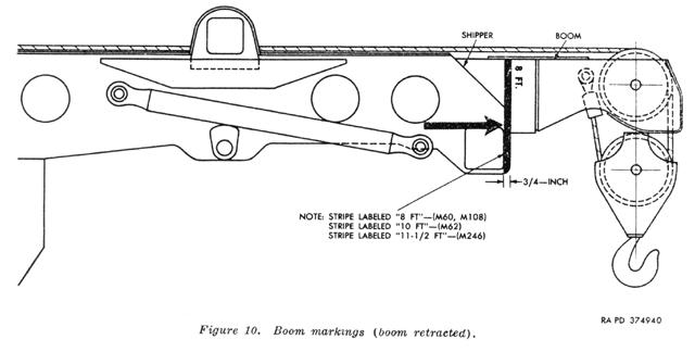
(c) To the right of and parallel with the stripe, mark "8Ft" in 2 inch letters.
(d) Mark a horizontal arrow on the shipper pointing to the stripe.
(e) Extend the boom to its maximum length.
(f) Measure from the "8 Ft" stripe. Scribe and mark 3/4, inchvertical stripes at intervals of 12 inches along the boom (figure 11).
|
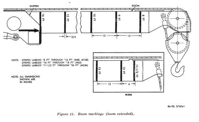
(g) Mark the second stripe "9 Ft", and each succeedingstripe consecutively through "16 Ft", in each case to the right of and parallelto each stripe.
(3) The procedure for Truck M60- is the same as for Trucks M60 andM108, except that the first stripe will be marked "10 Ft" and each succeedingstripe will be marked consecutively "11 Ft" through "18 Ft".
(4) The procedure for Truck M246 is the same as for Trucks M60 andM108, except that the first stripe will be marked "111/2 Ft". The second stripeis to be measured, scribed, marked, and labelled "12 Ft". Each succeeding stripewill be marked consecutively through "26 Ft".
f) Excessive Fuel Tank Pressure. This paragraph applies to tacticaltransport vehicles, and is intended to reduce the possibility of fuel spillage due to fueltank over filling and subsequent fuel explosion, regardless of fuel type.
(1) If the fuel tank filler cap is a relief valve type, but does notbear a warning decal reading "Pressurised: Open Slowly", the warning note"Pressure: Open Slowly" will be marked in 1 inch white letters on the cap or onthe fuel tank near the filler pipe.
(2) On fuel tanks, where a mark would be readily visible, measure 2inches down from the top of the tank and mark a 1/4 x 8 inch line, with the following notein 1 inch white letters: "Caution: Do Not Fill Above This Line". See figure 12.
|

(3) On vehicles where a mark on the fuel tank would not be readilyvisible, mark the following note in 1 inch white letters as near as possible to the fillerpipes: "Caution: Do Not Overfill-Allow for Expansion".
g) Maximum Safe Fuel Acceptance Rates. These marking instruction,-,for indicating maximum safe fuel tank filling rates are published for the benefit andsafety of personnel concerned with refuelling operations. The maximum safe fuel acceptancerate will be marked on each fuel tank near the filler cap. When the fuel tank is enclosedthe marking will be applied on the exterior surface of the enclosure adjacent to the fueltank Tiller cap access cover. The marking may be applied on one, two, or three lines,dependent on available space. When multiple lines are required the following examples willgovern.
2 Lines:
Max. Safe Fuel
Accept ______GPM
3 Lines:
Max. Safe
Fuel Accept
______ GPM
(1) Refer to table B for the safe fuel acceptance rates on allvehicles. As additional information becomes available it will be included in changes tothis technical bulletin.
(2) The marking will be in 1 inch white letters.
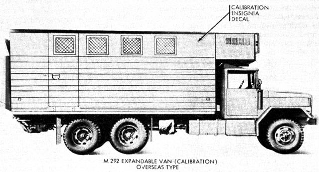
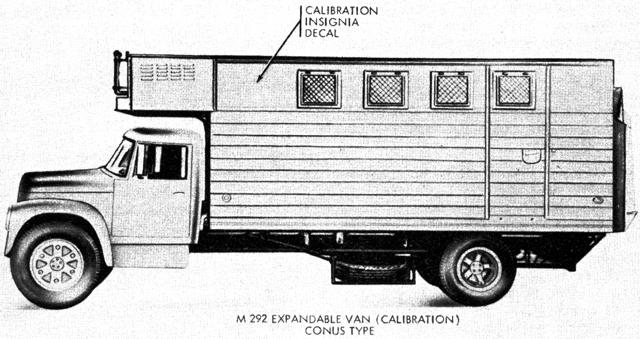
h) Calibration Insignia. All calibration vehicles will be marked witha calibration insignia in the form of a decal. These decals will be applied to the upperforward corners on each side of the M292 Expandable Van (figure 13). On other types ofcalibration vehicles (vans, panel trucks, etc.), the decals will be applied in the mostappropriate location on each side, dependent on surface size, window location, and surfacetexture.
| ||||
i) Capacity and Weight. All motorised materials handling equipmentwill have the capacity marked on each side. The marking will consist of the numeralsshowing the applicable pounds followed by the letters CAP. The actual weight of theequipment will also be marked on each side, in numerals, to show the applicable pounds,followed by the letters, MTWT. Letters and numerals will be one inch high, in the samecolour as the registration marking. Refer to figure 6.
j) Other Instructions. Other necessary technical instructions may bemarked on appropriate surfaces as required or authorised by the responsible command.
(1) Such markings will be applied in letters and numerals normally 1inch in height but not less than 1/2 inch.
(2) Colour of the markings will be white or black, whichever affords thegreater contrast with the surface colour. If practicable, the colour chosen will be thesame as the registration marking.
(3) Temporary instructions will be applied with removable vinyl markingsor gasoline soluble paint.
14 - Weight Classification.
a) All single vehicles with a gross weight of over 3 tons, and alltrailers with a rated payload exceeding 11/2 tons, are classified for the purpose ofbridge crossing, per FM 5-36. Each single vehicle and vehicle combination has aclassification number for empty, cross-country loading, and highway loading. Theclassification numbers are used to determine whether a bridge, correspondingly classified,can be safely crossed.
b) All applicable self-propelled vehicles not towing other vehicleswill carry a circular sign of 9 inch diameter with the vehicle's classification number inblack on a yellow background. This will normally be located on the front of the vehicletoward the vehicle's right side and below the driver's line of vision.
c) All applicable self-propelled vehicles towing other vehicles willcarry a sign similar in size, design, and location except that the classification numberof the vehicle combination will be shown with the letter C in red above the number. A 6inch yellow circle with the basic vehicle classification number in black will be marked onthe right side of the vehicle in a conspicuous location. The towed vehicle will besimilarly marked with its basic classification number.
d) When the classification number of the vehicle is not subject tochange, the marking may be applied directly on a suitable surface. On vehicles painted ingloss colours, the markings will be gloss yellow, Colour Chip No. 13538; gloss black,Colour Chip No. 17038; and gloss red, Colour Chip No. 11136. On vehicles painted insemi-gloss or lusterless colours, the markings will be lusterless yellow, Colour Chip No.33538; gloss black, Colour Chip No. 17038 and gloss red, Colour Chip No. 11136. When themarking is applied directly to vehicles painted in the same or similar colour, thecircumference of the circle will be outlined with a black circle .3/4, inch wide.
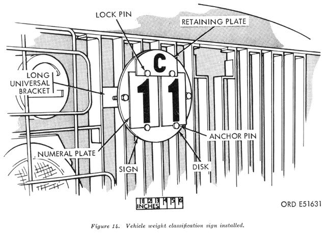
e) In usage's where the classification number may change, a sign kitwill be utilised which consists of a 9 inch metal disk, a retaining plate, and two sets offive different numeral plates. By installing the retaining plate, the numeral plates willbe locked in place. The sign has black numerals on a yellow background and a red C on oneside of the retaining plate (figure 14).
f) The following weight classification sign kit is being suppliedinitially with mounting brackets and hardware.
| Name | Part No. | Federal stock No. | Qty. |
| KIT: vehicle class sign, w/brackets and hardware Consisting of: | 9905-565-6267 | 1 | |
| 6 ea BOLT, MACHINE: hex-hd, S, cd- or zn-pltd, 5/16-24UNF-2A x 3/4* | 120741 | 5306-012-0741 | |
| 2 ea BOLT, MACHINE: hex-hd, low-carb-S, cd- or zn-pltd, 3/16-24UNF-2A x 1 3/4 | 123798 | 5306-012-3798 | |
| 1 ea BRACKET: unit, lg** | |||
| 1 ea BRACKET: unit, short** | |||
| 1 ea DISK: vehicle class sign, 9-in. | |||
| 6 ea NUT, PLAIN, HEXAGON: S, cd- or zn-chromate-fin., 5/16-24UNF-2B, 1/2w, 17/64 thk* | 120368 | 5310-012-0368 | |
| 2 ea PLATE: numeral, 0 one side, 1 other side | |||
| 2 ea PLATE: numeral, 2 one side, 3 other side | |||
| 2 ea PLATE: numeral, 4 one side, 5 other side | |||
| 2 ea PLATE: numeral, 6 one side, 7 other side | |||
| 2 ea PLATE: numeral, 8 one side, 9 other side | |||
| 1 ea PLATE: retaining, C on one side | |||
| 6 ea WASHER, LOCK: int-teeth, S, cd- or zn-pltd, 6/16 in. screw size | 138538 | 5310-013-8538 | |
| *Hardware items not required for the specific installation procedure will be returned to stock **Brackets not required for the specific installation procedure will be scrapped. | |||
g) In addition, a replacement kit, itemised below is authorised forthe replacement of lost or damaged numeral plates and retaining plates.
| Name | Federal stock No. |
| KIT: retaining and numeral plate replacement, for vehicle class signs Consisting of: | 9905-565-6268 |
| 1 ea PLATE: numeral, 0 one side, 1 other side. | |
| 1 ea PLATE: numeral, 2 one side, 3 other side. | |
| 1 ea PLATE: numeral, 4 one side, 5 other side. | |
| 1 ea PLATE: numeral, 6 one side, 7 other side. | |
| 1 ea PLATE: numeral, 8 one side, 9 other side. |
h) A vehicle weight classification sign kit, as below is authorisedfor the replacement of lost described herein, will be installed on the front or damagednumeral plates and retaining of each vehicle except:
(1) All trailers.
(2) Vehicles having a gross weight of 3
(3) Vehicles having standard classification numbers higher than 99.
(4) Vehicles having rated payloads of 3/4, to 11/2 tons. This exceptiondoes not apply to vehicles authorised for towing loads.
(5) Vehicles with fixed loads (such as tanks, self-propelled guns, etc.).
i) Front classification signs for vehicles included in h(3), (4), and(5) above will be painted directly on the vehicle. Side classification signs, whereapplicable, will also be painted directly on the vehicle.
j) These vehicle weight classification sign kits can be installed onvehicles in different ways. For example, in the case of Cargo Truck, M211, the sign can beinstalled on the brush guard, on the splash shield, or in an upright position on thefender. The choice of method is left to the using organisation.
(1) Location.
(a) The classification sign will be installed on the vehicle in one ofthe following locations:
1) Right front fender.
2) Right side of brush guard.
3) Right front section of hull.
4) Right side of centre front bumper splash shield.
(b) The sign will he placed below the driver's line of vision and willbe positioned so that it will not block headlamps, marker lights, blackout lights, airintakes, etc.
(2) Installation.
(a) On brush guard.
1) Paint the long universal bracket (channel) with rust-inhibitingenamel.
2) After the enamel has dried, position the bracket so that the two holesin the bracket align with two bolt holes (9 o'clock and 3 o'clock positions) in the sign.Assure that the flat bearing surface of the bracket faces toward the sign. Install onebolt (1 3/4 inches long) 123798, one washer 138538, and one nut 120368. Turn nut two orthree turns.
3) With the bracket in a vertical position, insert it between two bars ofthe brush guard at the desired location. With one hand, reach behind the brush guard andadjust the bracket to a horizontal position. With the other hand, install another bolt(1.3/t inches long), washer, and nut. Tighten both bolts, but apply only enough torque tosecure the sign to brush guard. Excessive torque will cause the sign disk to bend. Figure14 shows the sign installed on brush guard.
|
Caution: If it is found that the vehicle classification signseriously obstructs air flow to the radiator, as indicated by engine overheating, removesign from brush guard and Install sign elsewhere.
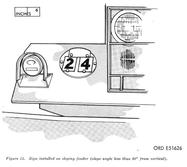
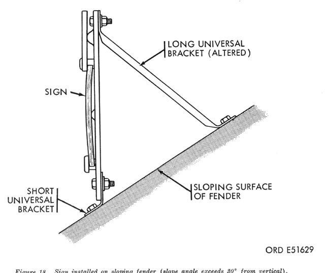
(b) On sloping fender. Install the sign as indicated in 1 and 2 belowonly when the slope of the fender is less than 30' from vertical. When the slope of thefender is more than 30' from vertical, install the sign in a vertical position, asoutlined in (c) below, to insure readability of the sign.
1) Position the sign in the desired location on the fender and, usingthe sign as a template, drill two 1%2inch holes in fender to align with bolt holes in thesign at the 9 O'clock and 3 O'clock positions.
2) Install the sign to the fender with two bolts 120741 (3/4 in.long), two washers 138538, and two nuts 120368. Tighten bolts securely (figure 15).
|
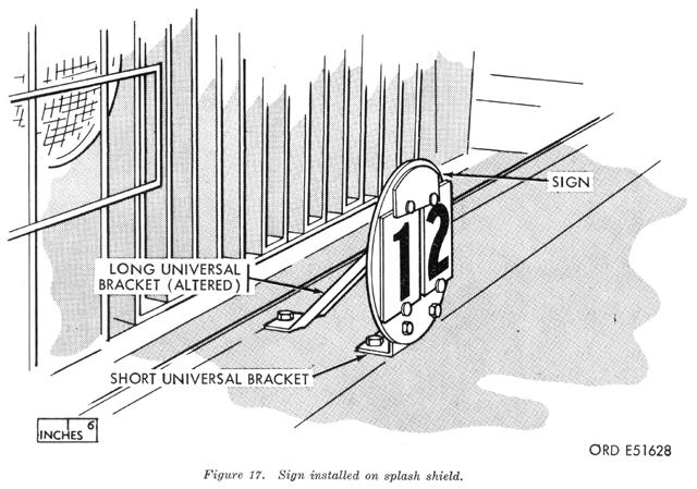
(c) In a vertical position on fender or on splash shield.
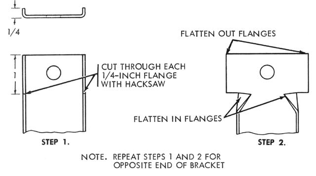
1) Alter the long universal bracket (channel) in accordance with figure16.
| ||||
2) Paint both the altered bracket and the short universal bracket(angle) with rust-inhibiting enamel.
3) After the enamel has dried, position the long leg of the shortbracket on the back of the sign and align two holes in bracket with the two lower boltholes in the sign.
Note. When installing the sign on a horizontal surface, position the short leg of thebracket so that it faces rearward (figure 17).
|
When installing the sign on a sloping surface, position the short leg of bracket sothat it faces forward (figure 18).
|
4) Install bracket to sign with two bolts 120741 (3/4 in. lg), twowashers 138538, and two nuts 120368.
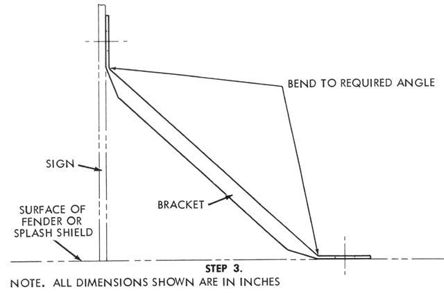
5) Position the sign in the desired location on the fender or splashshield. Bend short leg of bracket, as required, to conform to the contour or slope offender.
6) Using the short leg of the bracket as a template, drill two 11/32-inchholes in fender or splash shield.
7) Attach the sign to the fender or splash shield with two bolts (3/1 in.long), two washers and two nuts.
8) Secure the altered long universal bracket to the sign with one bolt(3/4 in. long), one washer, and one nut. (Insert bolt in hole located between two stacksof numeral plates on sign).
9) Drill an 11/32-inch hole in fender or splash shield to correspond withthe hole in the altered bracket and secure the bracket with one bolt (3/4 inch long), onewasher, and one nut. Figure 17 shows sign installed on splash shield. Figure 18 shows signinstalled on sloping fender.
k) Instructions for unlocking and locking the retaining plate is asfollows:
(1) Unlocking retaining plate. With the thumb of one hand, press downfirmly on one stack of numeral plates (figure19).
|
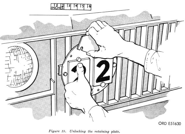
With the other hand, press down gently on the retaining plate and pivot the plate awayfrom the lock pin. To remove retaining plate completely, press down firmly on theremaining stack of numeral plates and free retaining plate from the other lock pin.
(2) Locking retaining plate. Assure that five numeral plates arestacked on each anchor pin with the two top plates showing the desired classificationnumber. If the vehicle is to be used in combination, position the retaining plate so thatthe red C on one side of the plate will be visible. If the vehicle is to be used singly,position the retaining plate so that the red C will not be visible. Press down firmly onthe top of one stack of numeral plates and slide the retaining plate onto the lock pinuntil the plate snaps in place. Repeat the procedure for the remaining stack of plates andlock the retaining plate to the remaining lock pin.
l) See table C for vehicle weight classification data. For vehiclesnot listed, or for which no similar vehicle is listed, refer to TM 5-312, only in theevent that no qualified engineer is available.
15 - Operation and DesignationPlates.
a) These plates as provided on vehicles and equipment will be kept clearand free from paint at all times.
b) Operation plates contain data or instructions on vehicle operationand will be installed within the normal view of the operator when in an operatingposition. The plates will include:
(1) Road speed plates. To prescribe the maximum permissible speed foroperation in each gear ratio and range.
(2) Shift diagram plates. To show the location of each position of thetransmission, transfer, and /or power takeoff.
c) Operation plates containing precautionary instructionsto avoid personnel injury or equipment damage will have a red background. This applies tonew plates of photosensitive anodised aluminium, conforming to type H, MIL-SPEC 15024.Existing plates will be replaced only when no longer serviceable.
d) Designation plates contain data pertinent to thevehicle or equipment, but are not required for actual operation. They will be located inconvenient position without creating confusion with operation plates. The plates willinclude:
(1) Name or identification plates. To show nomenclature,manufacturer, model, serial number, stock number, contract number, date of delivery to theGovernment.
(2) Data plates. To show empty weight, maximum payload, and/or grossweight, weight on each axle, and/or maximum towed load for highway and cross-country;centre of gravity empty and loaded, shipping cubage, overall and reducible dimensions, andother pertinent linear and angular dimensions.
(3) Servicing data plates. To show fuel capacity and minimum octane,cooling system capacity, draining instructions, tire pressures for terrain conditions,lubricant data for different temperature ranges, and other servicing data for the vehicle,components or equipment installed.
(4) Responsible agency plates. To show the Commodity Command or agencyresponsible for the procurement and/ or maintenance of the vehicle or its chassis, body,and /or equipment.
(5) Publication plates. To show the manuals (operator's, maintenance, andsupply) and lubrication order applicable to the vehicle.
e) Designation plates may be combined plates when spaceconditions warrant.
16 - Ambulance Marking - Military DesignVehicle.
a) Truck, Ambulance, 1/4 Ton, 4x4, M170 (Series).
(1) An 18 inch red cross on a 20 inch square white field will bemarked on each canvas side curtain directly to the rear of the canvas side doors.
(2) An 18 inch red cross on a 20 inch square white field will be markedon the rear of the vehicle. The upper half of this marking will be applied on the canvasrear doors and the lower half on the tail gate, centred with the centreline of thevehicle, in order that the full marking is shown when the rear doors are closed.
(3) A 45 inch red cross on a 48 inch square white field will be markedcentred on the canvas roof.
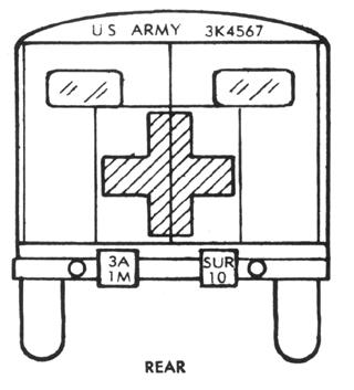
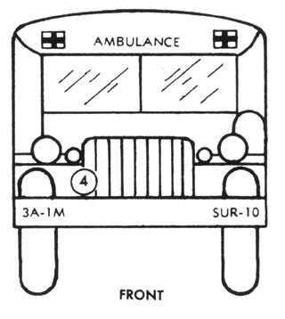
b) Truck, Ambulance, 3/4 Ton, 4x4, M43 (Series).
(1) The word "Ambulance" will be marked in 3 inch high whiteletters, centred three-quarters of an inch above the windshield.
(2) A 3 inch red cross on a 4 inch square white field will be marked toeach side of and in line with the word "Ambulance" above the windshield.
(3) A 36 inch red cross on a 39 inch square white field will be marked oneach side of the body below the roof joint and centred above the rear wheels.
(4) A 33 inch red cross on a 36 inch square white field will be marked onthe rear door panels directly below the windows and centred on the vertical centreline ofthe vehicle.
(5) A 60 inch red cross on a 64 inch square white field will be marked onthe roof 14 inches from the rear of the vehicle (figure 20).
| ||||||
c) Other Vehicles. Vehicles other than the ones enumerated which areintended for such usage and which are affected by international agreement concerning suchvehicles will be marked in a similar manner.
d) National Symbol. The National Symbol will not be applied to MedicalService vehicles.
e) Sizes. The' sizes of the red crosses specified are measured betweenthe ends of opposite limbs. Each limb of the cross will be a square having sides equal toone-third the size of the cross.
f) The Army Medical Service Insignia. The Army Medical Serviceinsignia consisting of a red caduceus on a circular white field will be applied to eachside of the ambulance. Caduceus to be Type 1, MS 16686.
(1) The circular white field will be 91/2 inches indiameter.
(2) The red caduceus symbol will be 6 inches high.
(3) The letter U will be centred to the left of thecaduceus symbol; the letter S will be centred to the right. These letters will be red, 11/2 inches high.
g) M170 Series Ambulance. The insignia will be applied each side ofthe vehicle body to the rear of the rear wheel.
h) M43 Series Ambulance. The insignia will be applied on each side ofthe vehicle body centred horizontally forward of the red cross emblem. The top of thewhite circle will be level with the top of the horizontal red cross arm. The legend"Army Medical Service" will be applied centred 31/2 inches below the caduceusinsignia, in 11/2 inch high white letters.
i) Ambulance Colour Markings. The following colours will be used forambulance markings, as applicable:
(1) Gloss red, Colour Chip No. 11136, and Gloss white,Colour Chip No. 17875 on vehicles painted gloss or semigloss olive drab.
(2) Lusterless red, Colour Chip No. 31136 andlusterless white, Colour Chip No. 37875 on vehicles painted lusterless olive drab.
17 - Military Police Markings-MilitaryDesign Vehicles.
a) Truck, Utility, 1/4-Ton, 4X4.
(1) On the M38, M38A1 and M151 Trucks, a white disc, 16 inches indiameter with the words "Military Police" in 3 inch black letters located.around the circumference of the disc, 1/2 inch from the disc edge, will be attached tothe centre of the spare wheel on the rear of the vehicle. The sign will be locallyfabricated from 16 gage sheet metal or thicker. The disc will be attached by means of abracket made from strap iron, 1 inch wide and 1/8 inch thick.
(2) In addition:
(a) M38 Truck. A detachable white sign, 5 inches high and 40 inches long,with the words "Military Police" in 3 inch high black letters will be mounted onthe windshield panel below the glass. The sign will be locally fabricated from 16 gagesheet metal or thicker, and will be bolted to the windshield panel with
inch bolts through existing holes in the panel.
(b) M38A1 Truck. A detachable white sign, 3 1/2 inches high and59 1/4, inches long, with the words "Military Police" in 3 inch high blackletters, will be mounted on the windshield panel below the glass. The sign will be locallyfabricated from 16 gage sheet metal or thicker and will be attached to the windshieldpanel with sheet metal screws.
(c) M151 Truck. A detachable white sign, 5 inches high and 36 incheslong, with the words "Military Police" in 3 inch high black letters, will bemounted on the windshield panel below the glass. The sign will be locally fabricated from16 gage sheet metal or thicker and will be attached to 'the windshield with sheet metalscrews.
(3) Motorcycle, solo, will be marked with a white band, 3 inches high,with the words "Military Police" in 2 inch high black letters, across the frontof the windshield directly above the horizontal support. When not obstructed by lights orsirens, the band may be placed below the support.
a) Application. The military police markings described herein will beapplied with pressure sensitive adhesive vinyl markers, non-Reflectorized and conformingto Military Specification MIL-D-8634B. For the vehicles identified above, pre-printedmarkers conforming to the size and shape of the fabricated signs will be applied directlyonto the signs before attaching to the vehicle. If pre-printed markers are not available,plain white vinyl may be used with the wording applied in individual black letters. Ifvinyl markers are not available and cannot be obtained, the markings may be applied in thestencil and paint method. The following colours will be used:
(1) Lusterless white, Colour Chip No. 37875.
(2) Gloss black, Colour Chip No. 17038.
Back to Colour and Marking of Military Vehicles Index Page.
Army Radio Sales Co. Home Page.