
By Major Breckinridge S. Smith USAF (Retired)
E-Mail smithab11@comcast.net
Web Site:
http://home.comcast.net/~smithab11/
Please Note: Army Radio Sales Co. and this Article's authors are not responsible for any damages or personal injury whatsoever, that may occur as a result of information provided here. This Article is published in good faith and as far as we can tell accurate. Make sure you understand the instructions before starting. Modifications to military radio sets may invalidate the suppliers warranty and reduce the re-sale value of the radio.
BC-611 (SCR536) B+ Battery Box
 The Completed Box |
|
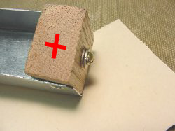
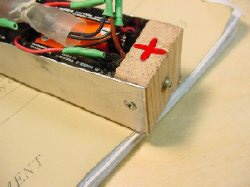
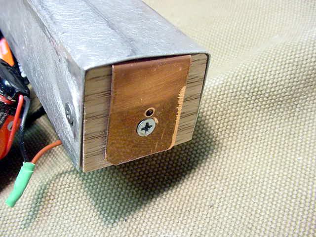
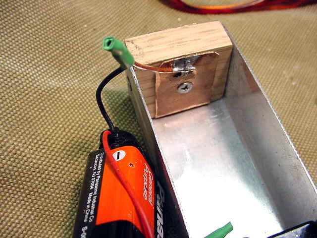
Introduction: The U shaped battery box holds 10 batteries and is fabricated from one piece of sheet aluminium, the ends are fashioned from standard oak stock with a brass bolt on the Plus end and a copper strip on the minus end. The nine volt batteries are wired in series, Plus end to the bolt, minus to the copper strip on the end of the holder. An in-line fuse is used for circuit protection. The batteries make a tight fit in the box, no battery clamps or holders are necessary. The completed box shown sitting on top of one of Robert W. Down's excellent reprints of the BC-611 TM. |
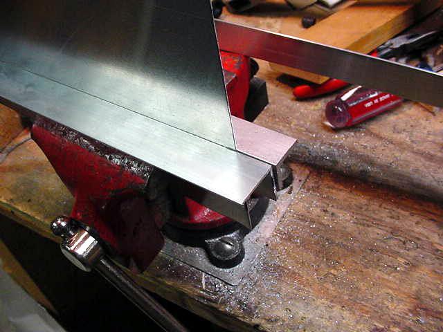
 The 0.025" Sheet Aluminium |
|
Don't like the prices of 9 volt batteries? I buy my 9 volt
batteries at the "Dollar Store", my most recent purchase had 2002 date codes
so they last for a couple of ham fests then I chuck them. But I always cover
the terminals with black tape prior to disposing, they have been know to
start fires in trash baskets. The 0.025" sheet aluminium is available from your home improvement centre. If you do a lot of sheet metal work angle snips are easier to use than straight ones, shown is an angle version. A Sheet Metal Brake is handy if you have them, If you do not have a
standard brake then use two pieces of angle aluminium held in a vice. Or use
two pieces of hardwood. Make your first bend and then scribe a line for the
second bend |
 A Sheet Metal Brake Is Handy |
|
 Pieces of Angle Aluminium In The Vice |
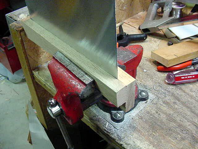 Two Pieces Of Hardwood |
|
 Making The First Bend |
 Trial Fit The U Shaped Tray |
|
Put your batteries in your tray and trial fit the U shaped
tray before making the oak end pieces. You will have a tight fit but the
tray must be able to move in the radio as the door is closed in order to
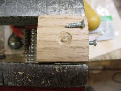
make contact with the base spring at the bottom of the radio. The end blocks are approximately 1-1/4 wide and are made out of 1/2 inch oak stock. Spend that extra dollar and obtain oak and the project will be very rugged. The end block sizes will vary slightly depending on your bending of the aluminium box to hold the batteries. Counter sink the inside of the Plus end piece to make it easier to solder
the positive wire. |
 Counter Sunk Hole |
|
 The End Blocks |
 #4 Flat Head Screws 1/2 Long |
|
The end blocks are held in place by #4 flat head screws 1/2
long. Obviously if they are any longer they may short out the brass bolt
used for the Plus Connection. Counter sink the aluminium for the flat head screws. This is necessary in order to allow the tray to slide in and out of the radio. The positive wire is soldered to the cut off BRASS bolt. Cut off the bolt after you are sure of a solid contact at both ends of the tray. I know its not red, I ran out of red Teflon wire. |
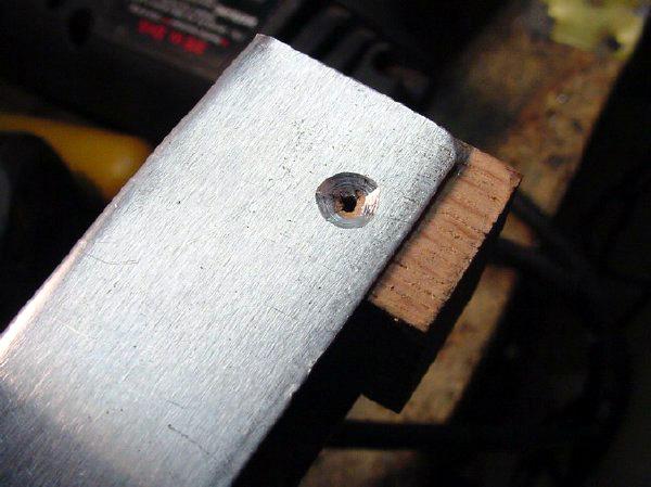 Counter Sinking The Aluminium |
|
 The Positive Wire |
|
 End Block In Place |
 The Plus Side |
|
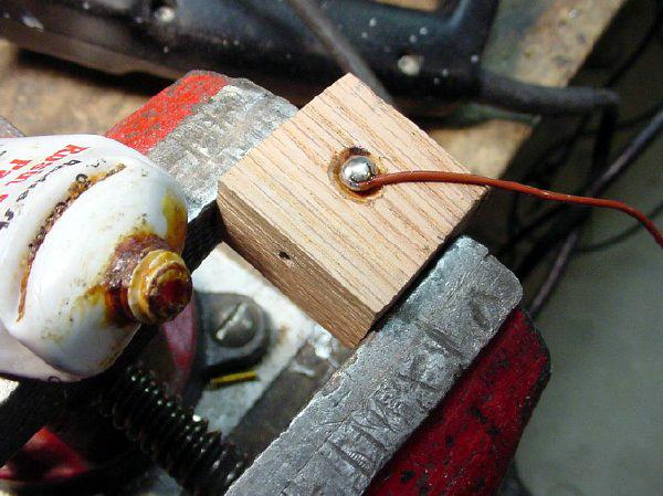
You can always lengthen the PLUS bolt by adding washers. If you all ready cut off the first bolt and it is now too short then put in a new bolt etc. Form a piece of 3/4 wide copper around the bottom of the MINUS block or ground connection. It is fitted around the bottom of the oak block and does not have to be insulated from the bottom of aluminium box. The wide copper strap on the Minus portion of the battery holder is necessary in order to assure good contact with the base spring located in the bottom of the radio. This copper strap is the minus connection for your pack and also makes the case of your home brew pack negative. The copper strap is held in place by a #4 screw on both sides of the end
block. Obviously you have to "stagger" the screws or they will collide. |
 The Plus End Of The Holder |
|
 The Copper Strap |
|
 The Copper Strap |
 Wire To The Minus End |
|
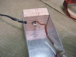
The end of the string of the 9 volt batteries is soldered to the Minus end copper strap on the inside of the block. |
|
WARNING: No one really likes to receive an electrical shock. Remember that the aluminium tray will be at ground potential and that by holding the tray and contacting the brass bolt you will be exposed to 90 volts. Don't do the standard battery "Tongue Test"! |
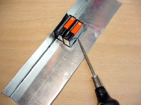
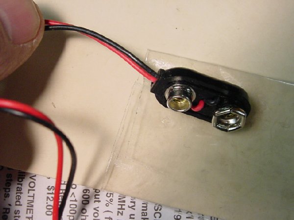 9 Volt Battery Connector |
|
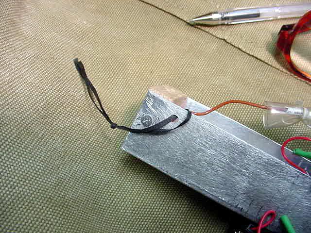
Their are many styles of 9 volt battery connectors , I
prefer the more rugged type, buy them at the ham fest or its Radio Shack
part number 270-324, very nice rugged connector. By twisting the wires as shown and apply heat shrink you will have a good "strain relief" system. Hot air shrinks the heat shrink, much better than a match. Borrow your wife's hair dryer! |
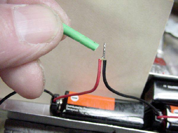 Twisting The Wires |
|
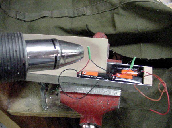 Hot Air Shrinking |
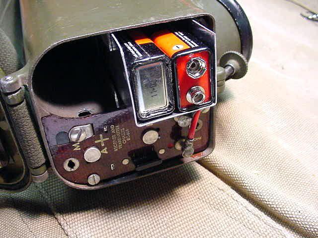
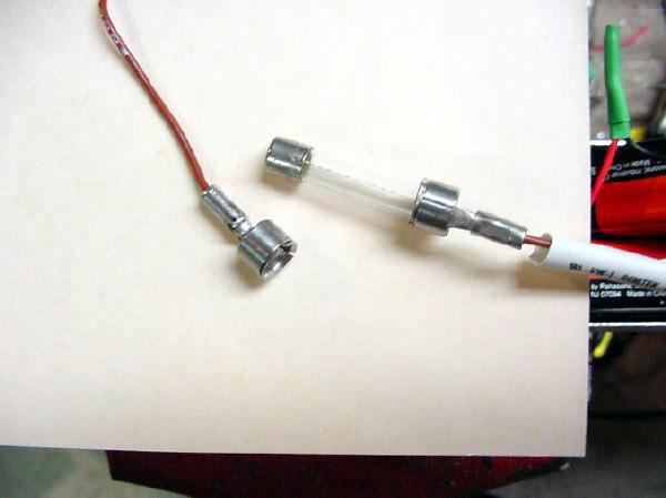 Fuse Holder |
|
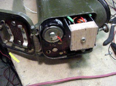
This type of fuse holder grabs the end of the fuse instead of just touching the end. The holder case was discarded. Heat shrink covered the connections for insulation and strain relief. Insulated tubing for housing the fuse holder. You can always check the status of the fuse as the tubing is clear. A finishing touch is a small lanyard to pull the box out of the radio for service. The servicing lanyard is located near the PLUS end. The Power Supply is now ready for the 3885 net at the Hamfest.
|
 Insulated Tubing |
|
 Small Lanyard |
|
 Ready Power Supply |
BC-611 (SCR536) B+ Filament Battery Supply
 The finished Unit |
|
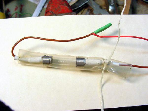
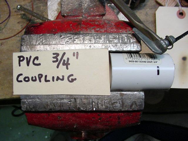
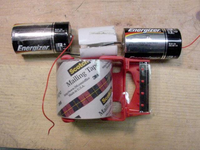
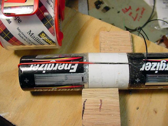
Introduction: Two D cells are wired in parallel and held together with a spacer made of a piece of standard PVC coupling and mailing tape. No modification to the BC-611 is necessary. Simple but easy to fabricate. More reliable and efficient than the FT-50 battery holder. See the finished unit. Parts List: PVC coupling, two D cells, some wire and mailing tape. Trim the PVC coupling to a length of 1 and 1/2 inches. The Red and black wires sneak down into the PVC slit to make the soldered contact with the batteries. The PVC coupling is slit length ways with a hack saw to allow access to
the ends of the batteries. Mailing tape is used to secure the assembly and
to provide insulation of the wires. |
 Required Parts |
|
 Trimming The PVC Coupling |
 The PVC Coupling |
|
 The Red And Black Wires |
 K9HXA Filament Battery Supply |
|
 K9HXA Filament Battery Supply |
|
 K9HXA Filament Battery Supply |
 The Finished Battery |
|
Here are some shots of Jerry's K9HXA filament battery supply. He turned the PVC and phenolic stock on a lathe and really did a fine job. I know the batteries are in parallel and there will be some "internal drainage" as one cell will be slightly different in voltage than the other. I measured less than one tenth of a milliamp current draw for a couple of days. Then I got bored with the test, best advice just forget about it. If you lose sleep over the drainage then unhook one wire after the mission. |
BC-611 (SCR536) Common Problems
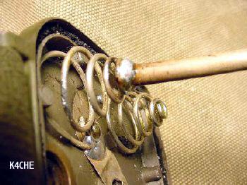
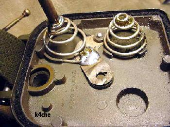 Re-Solder The Springs |
|
Do your self a favour and re-solder the springs to the main
ground contacts in the top of the radio. Re-solder the shaft of the "A" battery contact and spacer to the spring. Since we are dealing with only 1.5 volts a max effort should be made to improve the efficiency of the system, i.e. reduce losses due to poor electrical contact. Solder the area between the actual battery contact and the spacer shaft. |
 Re-Solder The Shaft |
|
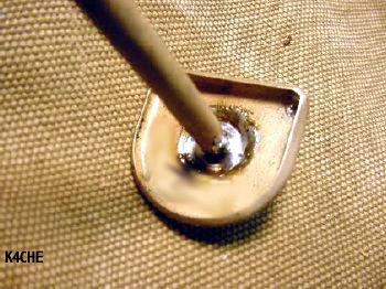 Re-Solder The Shaft |
Here are a few links for small battery data:
http://www.techlib.com/reference/batteries.html
http://www.wenzel.com/library/other-resources/battery-data/
Visitors to this page since 02 January 2003
Back to Your Articles Index Page.
Army Radio Sales Co. Home Page.