
By Major Breckinridge S. Smith USAF (Retired)
E-Mail smithab11@comcast.net
Web Site:
http://home.comcast.net/~smithab11/
Please Note: Army Radio Sales Co. and this Article's authors are not responsible for any damages or personal injury whatsoever, that may occur as a result of information provided here. This Article is published in good faith and as far as we can tell accurate. Make sure you understand the instructions before starting. Modifications to military radio sets may invalidate the suppliers warranty and reduce the re-sale value of the radio.
Introduction:
The PRC-64/Delco 5300 original battery is very hard to find, the battery number is a
BA-1509/PRC-64 and is described as a Battery Dry, 31.5 volts. After giving up my search
for the battery I decided to make a simple battery tray system using standard 9 volt
connectors, AA battery holders with a scrounged BA-48 battery connector as the main
connector from the tray to the radio. The tray is designed to fit into the original Delco
battery box and make connection as the tray is fully inserted. I was getting tired of
fooling around recharging Nicads and felt that for reliability the AA's were a better
choice. I searched for cell holders and connectors that were easily obtained and finally
decided on Radio Shack OTS (off the shelf) items. Their rugged 9 volt battery connector is
a very good quality and the 4 and 8 cell battery holders are fairly well constructed.
Circuit Overview:
I diode isolated all power circuits to prevent the operator from accidentally trying to
hook up those pesky 9 volt connectors backwards thus damaging the radio. The entire
battery tray slides in and out of the Delco battery compartment making it very easy to
service the batteries. The transmitter was designed for 24 volts but I am running it off
of 18 volts via one 8 cell and one 4 cell AA battery pack wired in series. The receiver is
powered by a 4 cell pack with one cell disabled. The power for the audio section of the
transmitter is obtained via a dropping resistor from the 18 volt pack. I abandoning the
idea of using 24 volts and having a 5 volt and 12 volt regulators, too complicated and
using Bill Lear's system of KISS, I stuck with the present system.
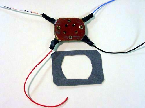 Connector from a BA-48 Battery |
|
Scrounge a connector from a BA-48 battery or similar dry dry cell. Solder
on new leads with spaghetti insulation. Additional insulation for the connecting leads with a cut out for the connector can be fashioned from a piece of oil paper or plastic. Those plastic bubble packs from the hardware store that take ten minutes to open and cut your hands to pieces have thin plastic that can be used. |
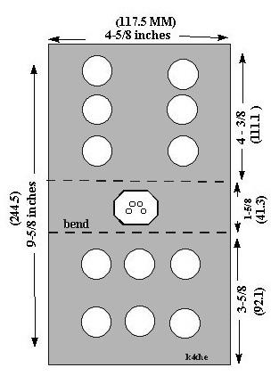 Dimensions of the battery box |
|
Fabricate a U shaped chassis for your pack. Holes were cut in
the sides of the chassis to aid in removing the pack from the Delco battery compartment
and to reduce the overall weight for tactical air shipment. A small bracket was formed to provide protection for the connector and to hold the battery boxes to the left and right of the connector. This piece is secured with 4-40 flat head screws to the side. This bracket forms a small centre compartment that can be used for storage of accessories but remember to protect the top of the BA-48 connector pins from shorting against any accessories that you store in this area.
|
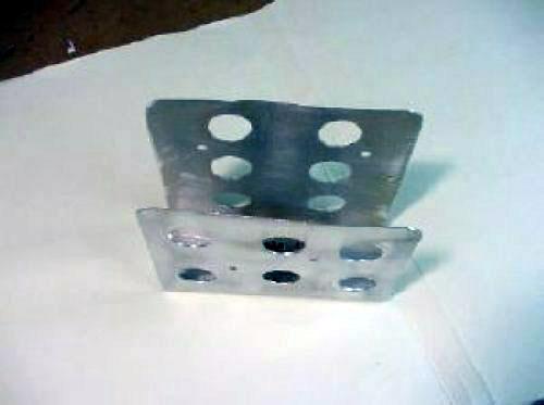
The bottom of the chassis has to be "flat" to insure that the connector will mate with the radio. You can make a cutting pattern outline on the bottom of your box by putting a small piece of carbon paper over the radio pins and press down with your uncut box, the pins will now be marked on your box. Drill and get out the old rat tail file. |
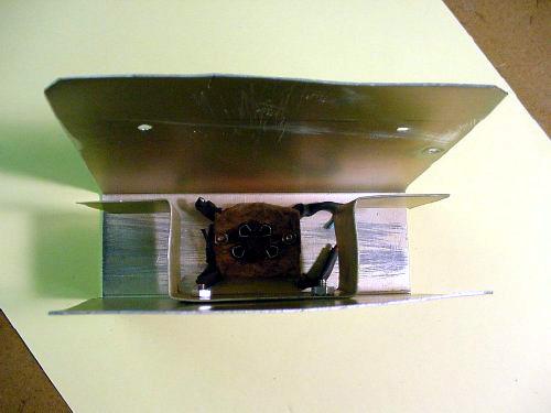
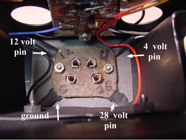 The BA-48 connector is in place and the additional insulation is positioned underneath the leads |
|
 Important: Flat head screws are used to mount the BA-8 connector |
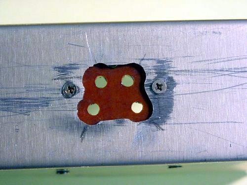
A distribution panel was made using a "carved" printed circuit board. Use a sharp hobby knife or Dremel tool to create rectangular shaped pads or "islands" for the connections. |
 Distribution Panel |
|
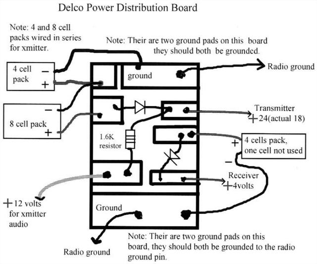 Distribution Panel Wiring |
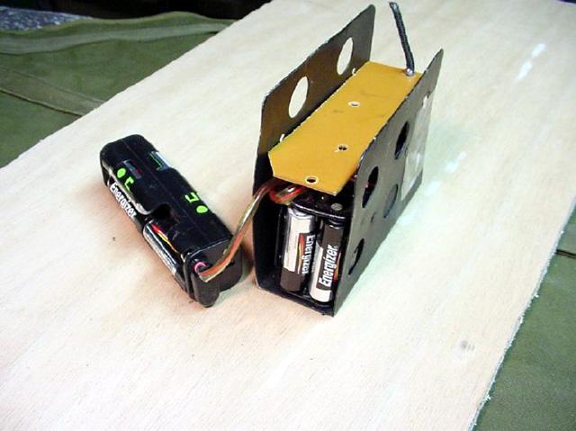
The receiver uses a total of 3 cells contained in a 4 cell pack, one cell holder is not used and contains a dummy cell. The dummy cell is constructed by using a discharged battery and running a wire from the top to the bottom of the battery. This technique helps the holder keep it shape and I also found that trying to solder to the holder and install a jumper destroyed the connectors as the plastic melted. The total voltage for 3 cells is 4.5 volts, I diode isolated this for reverse voltage protection and got an additional voltage drop and ran the receiver on the resulting 3.8 volts. The transmitter is powered from 18 volts comprising of a 4 cell and a 8 cell pack
wired in series. Each 4 cell pack will be installed vertically in the side compartments ,
the 8 cell pack will lay on top. |
 4 cell battery pack |
|
 Battery packs |
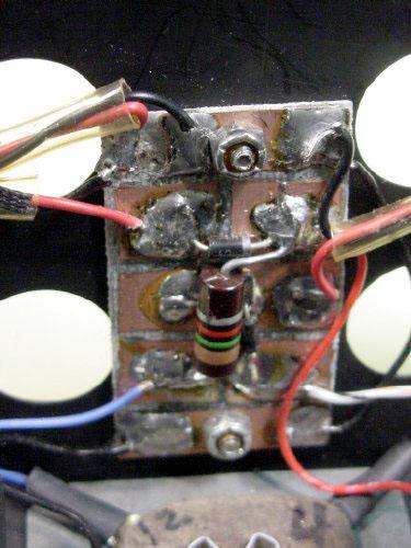
 Mounted distribution board |
|
The distribution board is mounted on the side near the BA-48 connector. A 1400 ohm dropping resistor was used to supply the 12 volts for the audio section. The tray was painted black because I didn't want any reflections during night operations while servicing the battery. |
A Word of caution about the small cell battery cases, they have exposed terminals when the main 9 volt male-female connector is not connected. In addition all of the packs that I used had exposed rivet's, if you leave the batteries in their cases then store the cases properly. Remember that the AA battery rating when new is approximately 1500 to 2000 mAh. Best bet is to remove the batteries or at least remove one of the batteries to disable the pack. Those small 9 volt batteries that float around on your work bench are rated at 500 mAh and are also dangerous, don't just throw them in the trash when you think they are slightly weak, cover the terminals with tape.
Here are a few links for small battery data:
http://www.techlib.com/reference/batteries.html
http://www.wenzel.com/library/other-resources/battery-data/
 Insulate all exposed rivets |
|
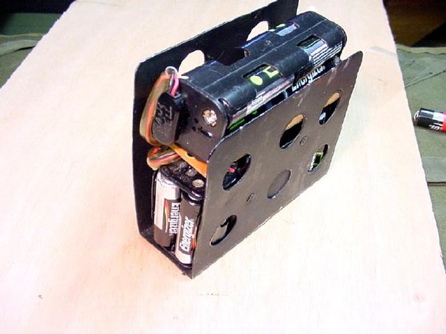
 The plastic divider is in place |
The completed project. Leads to the battery case connectors are covered with clear tubing. The small plastic divider piece is in place to separate the first layer of batteries (left and right batteries) from the upper 8 cell pack. All the batteries are in place and there is still plenty of room left when the cover is put on. Notice that part of the tray sticks above the battery box for ease of removal.
|
PARTS LIST: (Partial, Radio Shack)
270-324 "heavy duty" battery connectors.
270-324, 8 Cell battery pack.
270-407A, Diodes 276-1102 (1N4003) or use a 276-1103 (1N4004).
The transmit audio dropping resistor that I used was a 1 watt, 1600 ohm, its not very critical. If you can't find a 1 watt, try experimenting with some one half watt resistors in parallel such as two 3K resistors.
Visitors to this page since 23 June 2002
Back to Your Articles Index Page.
Army Radio Sales Co. Home Page.