By Ray Robinson
VK2ILV
E-Mail robinson@srsuna.shlrc.mq.edu.au
The R-1155 is an English LF and HF super heterodyne receiver covering from 75kHz to 18.5mHz in 5 bands, with D/F (Direction Finding) and homing functions. This receiver started development in 1939 by the Marconi Wireless Telegraph Co and was called the AD.87B/8882B to replace the pre-war T1083 and R1082. The R.A.F. designation was the R-1155 and the corresponding transmitter was the T1154, the first units being installed during WWII in June 1940 mainly in Lancaster Bombers as well as other aircrafts. These were still used into the 1950s. Several companies manufactured them, including Marconi, Ekco, Plessey, Philips, and the Gramophone Co. (EMI). They were fitted to many aircraft like the Avro Lancaster and the deHavilland Mosquito. They were imported into Australia after the War to be used in Lincoln bombers. Although they were used mainly in aircraft, later in the war they were fitted to small boats (N suffix), and also to vehicles (115, 115B, 130, 131).
The receiver has 10 valves of which 3 are for the D/F and one is a Tuning Indicator (magic eye). There are 6 used for the super heterodyne receiver. The receiver has an RF stage, a mixer/oscillator, two IF stages, an AVC and BFO stage, a detector, an audio amplifier, and a magic eye tuning indicator. The D/F circuitry has two valves as aerial switching and multi-vibrator, and a meter switch. It can have 3 aerials, a fixed wire type, a trailing aerial, and a D/F loop. It has 11 controls of which 5 are for D/F only.
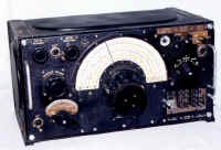
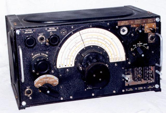 R-1155 Radio Receiver |
The receiver is small and light, and has a good feel when tuning in stations. It is fairly sensitive and reasonably stable, although drifting a bit during warm-up. The fixed frequency BFO is not a limitation when tuning CW or SSB. There are several controls that are superfluous for general listening. The electrical design is quite interesting, especially the D/F circuitry. It weighs 25 pounds. |
| Frequency Coverage: | |
| Band 1 | 7.5 Mhz - 18.5 Mhz |
| Band 2 | 3.0 Mhz - 7.5 Mhz |
| Band 3 | 600 Khz - 1500 Khz |
| Band 4 | 200 Khz - 500 Khz |
| Band 5 | 75 Khz - 200 Khz |
| Some models had a 1.5-3.0 Mhz band instead of the 75-200 Khz band. | |
It is rare to find an R-1155 with the D/F controls intact, as they have usually been removed, being of little use to non D/F activities. Quite often the D/F switching valves and components are missing, and an AC power supply built in. The Jones plugs on the front may have been replaced, and an "S" meter may be there instead of the magic eye tuning indicator. The dial window is usually discoloured with age and sometimes bulging out due to internal operating heat over time. The coloured dial scale may have faded. The scale is in Red, Yellow and Blue, to match the transmitter bands, and other parts of the frequency scale are in black. The internal wiring may use rubber covered wire, which goes hard and disintegrates when disturbed.
| Different Models | ||
| Model | Case | Notes |
| R-1155 | Aluminium Case | |
| R-1155D | Steel Case | |
| R-1155A | Aluminium Case | Filters fitted to prevent interference from MF transmitters |
| R-1155E | Steel Case | MF filters |
| R-1155M | Aluminium Case | MF filters. For use only at ground schools (due to use of corrosive flux) |
| R-1155B | Aluminium Case | Same as A but HF chokes added to prevent interference from radar. |
| R-1155F | Steel Case | HF chokes. |
| R-1155C | Aluminium Case | Same as A but modified for HF. D/F obsolete. |
| R-1155L | Aluminium Case | Same as B but frequency range changed to 200-500kHz, 0.6-18.5mHz. |
| R-1155N | Steel Case | Same as L |
| The L version was used for Coastal Command and the N version was for Marine craft. | ||
Normal Controls
The main controls are the TUNING knob, to tune in the desired frequency, the FREQUENCY
switch knob to select the desired frequency band, and the INCREASE VOLUME control which is
an audio gain control when AVC in on and is an RF gain control when the AVC is off. There
is a switch labelled HET which turns on a beat frequency oscillator for receiving CW. The
heterodyne frequency is fixed and can only be adjusted through a hole in the front panel
with a screwdriver. I have used this receiver for SSB and found that frequency adjustment
is not necessary. There is a FILTER control that switches in an audio filter to reduce
unwanted noise. On the right is a MASTER switch. In the OMNI (directional) position (which
has a symbol of a circle with a dot inside it), it uses the main long wire aerial with the
AVC off. The next position turns the AVC on. This switch also turns on the D/F
functions.
D/F Controls
It has several controls for D/F which are enabled by the MASTER switch. In the
BALANCE position, a dummy aerial coil is switched in, and the receiver electrical
characteristics can be balanced by observing the Visual Indicator and adjusting the METER
BALANCE control until the Visual Indicator needles intersect on the centre line. The
needles can be moved up and down the centre line with the METER AMPLITUDE control. This
may have to be adjusted later when the strength of the homing signal changes. In the
VISUAL position, the aerials are connected, and the difference in the phase of the signals
from the aerials shows the deviation from a course to a transmitter, which enables the
aircraft to fly toward it, and home in on it. This uses the loop aerial and the
fixed aerial. to do visual homing, switch to VISUAL. Set the loop "athwarthship"
(i.e. to a zero scale reading) and ask the pilot to alter course until the needles
intersect on the centre line. Then alter course slightly and observe the deflection. If
the course is offset a few degrees to the left and the needles cross to the right, then
this is the correct course. If they intersect also to the left, then the station is
astern, and a 180 degree turn should be made.
The METER DEFLECTION control can be set to HIGH or LOW which narrows the cardioid aerial pattern for easier homing. The SWITCH SPEED can be set to HIGH or LOW which changes the switching rate of the multi-vibrator. Since the multi-vibrator can be heard as a buzz on the received signal, the radio operator can listen to CW or voice, and change the buzz to make the signals more intelligible (HIGH for CW and LOW for R/T), during homing. The last position is a "FIGURE-OF-EIGHT" position (shown on the front panel as the number eight symbol) and this uses the loop aerial only, to determine transmitter direction, the 8 representing the loop aerial pattern. Since the transmitter direction can be true or reciprocal, an AURAL SENSE switch can be set to L or R to determine the correct direction. This switches in the fixed aerial, and will make the signal louder or softer. To do this, first select the FIGURE-OF-EIGHT position and rotate the loop to a null, and observe the loop scale reading. This will be the true course or the reciprocal. To determine which, rotate the loop Reducing the scale reading, and push the AURAL SENSE switch to R. If the signal increases, the course is Right. This is the RRR rule (Reduce, Right, Right). If it decreases, rotate the loop through 180 degrees and repeat the procedure.
Main Tuning Knob
In July 1941 there were operational problems reported to Marconi concerning the Type 13
main tuning knob. This is a concentric knob, with the inner smaller knob giving a 1:1
ratio and the outer larger knob giving a 100:1 ratio for fine tuning. Ekco was given the
task of investigating and solving any problems. They found that when the fine tuning knob
was adjusted it rotated the coarse tuning knob in error. On inspection of receivers fitted
to aircraft, they also found that the radio operator's gloves tended to foul the coarse
tuning knob. They found loose grub screws on the cork friction disc as well.
Ekco designed a new knob with the coarse drive at the rear, and a large fine tuning knob at the front. The coarse drive was changed to a 4.5:1 ratio and the fine tuning drive to an 80:1 ratio. The knob is distinctive looking in that it is larger and hangs slightly out and below an aluminium casting. It has a better feel than the original one, and is fitted to this receiver. It was given the designation Type 35. It was submitted to the Ministry of Aircraft Production in March 1942 and a program of retrofitting was adopted. However, I have only seen 2 receivers with this knob, most having the original type.
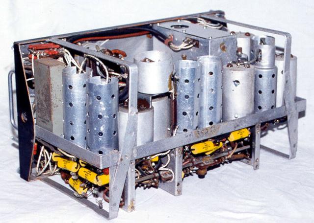 R-1155 Radio Receiver Internal View |
Restoration I have had this receiver for over 20 years, as it was bought by a friend from Chris Cowan VK2PZ, and then passed on to me. When I finally started to restore it 3 years ago, I had to remove the years of dust and dirt and take stock of what was missing. The front panel was dirty, chipped, and dented so it was straightened and repainted, as was the case. It had been dropped on the front, so the broken Type 13 knob was replaced with a Type 35 that I had picked up at a junk sale. This also had the type A8882B and Serial number 404 designation plate on it, which I used as this receiver had no nameplate. |
The VOLUME control was bent inwards, and it was discovered that by removing the 4 screws on the plate holding it, allowed the whole dual gang control VOLUME to be pulled through the front panel. On inspection, it looked impossible to access it from the inside! The plate was straightened and the control returned to its position. All the knobs and nameplates were cleaned. There were only 3 screws holding it in the case, so a new knurled screw was made on the lathe and all front panel hardware was zinc plated. Other screws were replaced with new nickel plated screws. The Jones plugs that had solder on the pins were replaced. The dial glass (Perspex!) was bulging out and discoloured, so a new piece was made.
Most valves were missing, so these were procured, and fitted. The valve shields were missing bar one. The one visible at the right hand rear was the only one that came with the receiver, so I made the others to look the same, apart from the stepped side, which proved too difficult. I will fit the correct ones as I find them. They had a top cover as well. All the bypass capacitors were in slim cylindrical metal cans that mounted on the chassis next to the valves, with wires coming out the bottom. Some cans had more than one capacitor in them. They were missing from this set, so I had to put normal pigtail capacitors under the chassis. They are the yellow capacitors visible in the photograph. The BFO cover was missing, so I made that. I do have the under chassis coil box cover, although it was not fitted when the photo was taken. The original rubber covered wire was brittle, and broke when disturbed, so I decided to replace it. I identified each end of a wire, removed it, replaced it with cotton covered wire, and marked it off the circuit diagram. I tested each capacitor, resistor and coil as I went through the circuit, from the RF stage to the audio. It took a year.
The set was then powered up and aligned. It all aligned OK except for one oscillator coil that needed a little extra padding, to correct tracking. It worked well for a while, but would suddenly stop. I eventually discovered 200VDC on the mixer grid, for Band 3. This proved to be an insulation breakdown between the RF plate primary and the mixer grid secondary. I reinsulated and rewound the primary for this coil.
Electrical Design
The electrical design is rather interesting. It is a 6 valve super heterodyne receiver.
The receiver has a VR100 RF stage, a VR99 mixer/oscillator, two VR100 IF stages, a VR101
AVC and BFO stage, a VR101 detector, and audio amplifier.
The RF stage can have 3 aerials, a long wire trailing one for LF (the lower 3 bands), a fixed aerial for HF (the upper 2 bands), and a loop for D/F. On this model, all the aerial leads have RFC chokes in them, to stop interference from RADAR transmitters on the aircraft. On 8th July 1941 Coastal Command informed the Marconi Company that there was a heterodyne due to Radio Athlone in Northern Ireland on 565khz. This resulted in three 560kHz traps (or "rejecter circuits") being fitted to stop any signals getting into the mixer via the RF stage. There is one in the RF amplifier grid (the open topped can above the chassis in the rear photograph), and another in the RF amplifier plate circuit. There is a third one in the mixer grid circuit, which is only switched in for bands 3,4 and 5, to stop any instability. The IF frequency is 560kHz and is 4.3kHz wide. The IF cans do not contain transformers as such. They contain a slug tuned plate coil from the previous stage and a slug tuned grid coil for the following stage, but they are not inductively coupled! The 2 coils are mounted at right angles and capacitively coupled. From the IF stages, the signal goes to a diode detector and AF amplifier valve.
There is a high pass RC filter which can be switched in, to filter out any audio below 300Hz, intended to remove aircraft electrical and ignition noise. The VOLUME control changes the audio input to the triode output valve, when AVC is on, and changes the bias when the AVC is off . There is a transformer output for headphones, but the plate is also brought out to the Visual Indicator Jones plug, so this male plug has exposed HT on the pins. Another triode is used as the BFO and this oscillates at 280kHz which is half the IF frequency. This is to prevent the incoming signal "pulling" the BFO frequency. This is injected into the last IF coil, and relies on the second harmonic to achieve an audible beat note for CW. It has a fixed trimmer for adjustment which can be reached through a screw hole in the front panel. The BFO can be switched on with the HET switch. The diodes in the BFO valve are used as the AVC rectifier. The AVC is applied to the IF valves, the mixer and the RF amplifier. There is a magic eye tuning indicator connected to the AVC line. Any strong signal causes more of the florescent screen to glow, reducing the shadow. The HT negative lead does not connect to chassis, but goes through some resistors to develop bias for the valves. When the MASTER Switch in in the OMNI or FIGURE-OF-EIGHT position, the AVC is off, the VOLUME control becomes an RF gain control and the loop can be used to determine a NULL. The SENSE control is a centre-off spring loaded switch, which applies power to either of two switching valves. These switch in the fixed aerial to one or the other side of the loop, and the phase of the incoming signal will make the volume rise or fall.
The D/F circuitry consists of 3 valves, which contribute nothing to the super heterodyne receiver. They instead control the input and output of the receiver in an interesting way. Two of the valves act as an RF switch and connect the fixed aerial to the sides of the loop. The SENSE control turns either one of them on, for aural sense determination. The valves are a VR99 triode-hexode. The triode part of the 2 valves are connected as a multi-vibrator which can run at 30Hz or 80Hz. They run when the MASTER switch is set to BALANCE or VISUAL. When the multi-vibrator is running, it alternately turns the 2 switching valves on, which connects the fixed aerial to alternate sides of the loop. The signal is then stronger and weaker, depending on the phase of the signal from the loop and the fixed aerial. The audio output is correspondingly louder and softer. The audio output is connected to a VR102 dual triode. This acts like a switch as well, also controlled by the multi-vibrator, and switches the output to the Visual Indicator. The Visual Indicator has two independent moving coil meters in one case, with overlapping needles. If the signal is equal, the needles cross on the centre line, and if there is a difference in strength, they cross to one or the other side of the centre line. One of the diodes in the audio output valve is used as a limiter to ensure that the Visual Indicator is not overloaded.
 R-1155 Radio Receiver Visual Indicator |
Visual Indicator This is used for homing or D/F. The instrument is normally in front of the pilot and/or the navigator. When the aircraft is flying towards the homing signal, the needles cross on the centre line. If the aircraft deviates, then the needles cross to the left or right of the centre line to indicate that you are off course, and need to correct. If they cross to the left, then you need to turn to the left to correct your course, and similarly for the other side. As you approach the homing transmitter, the needles will move higher up the centre line. You can reduce this with the METER AMPLITUDE control. |
If the homing signal seems too broad to get an good course, then the METER DEFLECTION switch can be used to make it more accurate by switching between the HIGH and LOW positions. This control makes the cardioid pattern sharper. As you fly over the homing transmitter, the needles will collapse, and then restore to their original level as you fly away, however the sense is reversed.
Power Supply
The R-1155 is normally connected to a Type 34 or Type 35 rotary transformer which
runs from the aircraft electrical system. These are controlled by the main switch on the
T1154 transmitter. There is also a Type 114 mains power supply that can used for bench
testing both the receiver and the transmitter. The HT is 220V but the negative is not
earthed. It comes into the receiver, and goes through some resistors to chassis, so that a
negative bias is developed. The LT is 6V DC which also comes via the transmitter. It all
enters the set through the extreme right hand connector. I have made a small power supply
to allow the receiver to be used from 240V AC mains, independently from the transmitter,
as I have none of the correct power supplies. Here is the circuit. The R-1155 audio output
is intended for headphones, so I have added a power amplifier using a 6V6 and speaker
inside the box as well. When the set is to be used for homing, the Visual Indicator is
mounted in front of the pilot and/or navigator, so that the direction to the homing signal
can be followed. It is connected by the middle Jones plug on the receiver. I have mounted
this in the power supply box. The fixed and trailing aerials are connected through the
right Jones plug, which also carries the power. The left Jones plug connects to the loop.
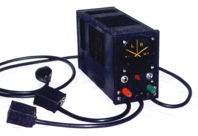
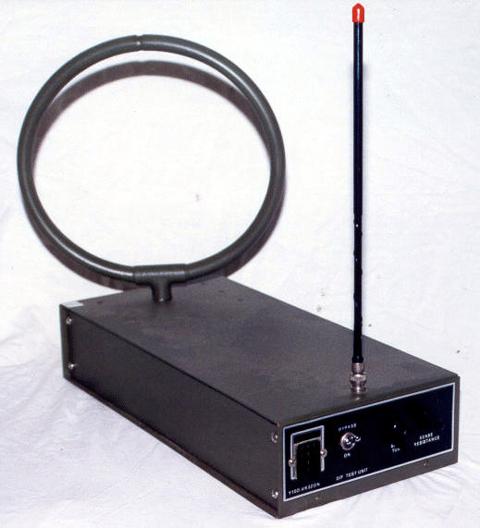 D/F (Direction Finding) Test Set |
D/F (Direction Finding) Test Set I built this unit to test the D/F of the R-1155 and to demonstrate the homing facility using the Visual Indicator. The D/F loop will turn (by hand) and shows how a the FIGURE-OF-EIGHT switch position can be used for Direction Finding. The small whip aerial is used as a sense aerial (normally the 21 foot long fixed aerial on the actual aircraft), Since the whip doesn't have the gain of the fixed aerial, I have built a small IC amplifier in the box. When coupled to the R-1155 this produces a cardioid pattern. The L/R switch on the receiver produces a loud or soft signal indication, so that the correct bearing or the reciprocal can be determined. When the switch is set to Visual, you can hold the box in your hands, and as you move it around, the Visual Indicator shows the direction to the transmitter, and as you move it off course, to the left or right, the Visual Indicator needles cross to the left or right of its centre line. |
References
Radio Goes to War and a Legend is Borne, Chas E. Miller, Radio Bygones Number 1,
August/September 1989, P3-5, 27.
Tuning for Perfection, George Rawlings and Max Westly, Radio Bygones, Number 45,
February/March 1997, P14-17.
R.1155 intermediate frequency, Feedback, Radio Bygones Number 48, August/September 1997,
P35-36.
Receivers Types R-1155, R-1155A and R-1155B, Air Publication AP1186, Vol 1, SECT 3, CHAP 6
Receivers Types R-1155, R-1155A, B, C, D, E, F, L, M and N, Air Publication AP2548A Vol 1,
September 1947
R-1155 Receiver Modification, G. W. Canning, VK3ZIC, Amateur Radio, February 1962.
Visitors to this page since 20 February 2000
Back to Your Articles Index Page.
Army Radio Sales Co. Home Page.