By Ray Robinson
VK2ILV
E-Mail robinson@srsuna.shlrc.mq.edu.au
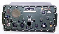
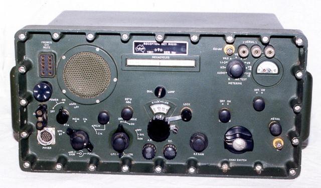 R-5223 Radio Receiver |
This is an Australian made communications receiver, manufactured by T.C.A. (Telecommunication Company of Australia, a subsidiary of Philips). It was designed and made in Adelaide in 1961 for the Australian Army and called the Reception Set R-5223. The receiver covers 1.5mcs to 30.5mcs in 29 bands, each band being 1mc wide and centred on the frequencies 2 to 30mcs. It is a 13 valve super heterodyne receiver using double conversion ( the 2 lower bands are single conversion only ), and is suitable for CW, MCW, and VOICE. It is in an aluminium watertight case, and even the speaker is waterproof. Flanges can be added to the side of the case to rack mount the unit. The power requirements can be selected to be 240VAC, 110VAC, or 12VDC. |
Performance
The receiver is easy to use, with a nicely spread out linear frequency scale. It is easy
to tune in stations, but scanning through the spectrum involves switching in the
many bands and moving the dial pointer from one end of the dial to the other to continue
tuning. It has 2 dial windows. The top straight one is the linear dial that has a pointer
moving 500kcs either side of the selected megacycle tuning range. The lower fan shaped one
has a circular dial marked in kcs, also with linear graduations. The dial pointer of this
one can be set with the calibrator. The tuning knob would be better if it were larger and
had a flywheel. It is smooth and does have a lock. The dial calibrations are in black
lettering for all the double converted bands. The lower 2 bands are calibrated in red, and
read in reverse. This is because they are lower in frequency than the first IF. The
receiver suffers from having only a BFO and so SSB tuning is not as easy as it could be.
It only has one filter for adjusting bandwidth. Having selectable Collins mechanical
filters would be an asset.
Controls
The receiver has a POWER ON/OFF switch which will also turn the speaker ON and OFF.
The FUNCTION switch has a standby position where only the valve heaters are on, and RT,
MCW, CW positions for the reception mode. When the FUNCTION switch is on RT, the AGC is
switched ON. When the FUNCTION switch is on CW, the BFO is on and the note control is
located in the centre of the LTR (limiter) control. There is another MCW and CW position
which connects a filter in circuit, tuned with the FILTER control. This has a 250 cps pass
band and is tuneable over the audio range. When the filter is switched out, this knob
becomes a high cut audio filter, or TONE control. The AUDIO GAIN control is in the centre
of the FUNCTION switch. There is a 4 position LTR switch, which allows for single or
double diversity, with or without the LIMITER. When in double diversity, the IF
output connectors and the AGC connectors of the 2 receivers should be connected together.
There is a main tuning knob which is used to select the frequency. This has a KILOCYCLES
scale with an adjustable pointer (called ZERO ADJ.) and a MEGACYCLES scale. There is a
dial LOCK for the tuning control. There is an RF GAIN control to change the receiver
sensitivity. There is a BAND SWITCH to select the 29 bands, each 1mc wide. The dial lights
can be controlled from the LIGHTING ON/OFF switch. The CAL switch will turn a 1mc crystal
calibrator ON, which allows the dial pointer to be accurately set with the ZERO ADJ. knob.
The AERIAL trimmer will tune the aerial.
The meter on the front, has many uses, selected by a switch. It is usually used as an S meter. It can also be switched to show Audio level, the High Tension voltage, the current drawn by the valves V1-V3, V4-V5, V6, V7, V8, V9-V11, V12-V13, and Test. When in the INT. TEST position, the meter is switched to two probes which can be used to measure voltages inside the unit. The probes are normally stored in a fibre tube on the Left Hand Side of the receiver, near the power transformer. The internal photo shows them extracted and ready for use.
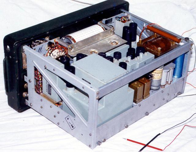 R-5223 Radio Receiver Internal View |
The receiver is a double conversion receiver on most bands. It is designed as a single conversion receiver for 2 bands, and with a frequency converter used to provide coverage for the other 27 bands. All coils are permeably tuned which results in a linear frequency scale. The 6BA6 RF amplifier is coupled to the 6BE6 first mixer, which uses a 6AU6 oscillator. This oscillator is crystal controlled, with 9 crystals in the range 6 to 14 mcs. The oscillator is off for the lower 2 bands, and so the RF passes straight through the mixer, unchanged. The first I.F/second mixer uses a 6BE6 with another 6AU6 as the variable oscillator. The first I.F. is variable in the range 1.5 to 2.5mcs for all odd bands and 2.5 to 3.5mcs for all even bands. On the two lower bands (1.5-2.5mcs, and 2.5-3.5mcs), the variable IF is actually the receive frequency. On all other bands, an extra mixer is switched in, and various crystals are used in the local oscillator to shift the received frequency down to these 2 bands. |
The second I.F. is 500kcs and uses two 6BA6 valves with I.F. transformers between them. The output from here goes into the 12AT7 detector and limiter. The audio then goes to another 12AT7 used as an audio preamplifier and filter, and then to a 6AM5 power output valve. There is a 6AV6 used as the AGC rectifier and amplifier, with a 12AT7 providing an AGC threshold and a BFO. The AGC is applied to the two IF stages, both mixers and the RF stage. A calibrator which uses a 12AT7 can be switched on which allows the dial pointer to be adjusted to 100kcs graduations.
The aerial input can be 70 ohms unbalanced using a BNC connector, or 70/600 ohms balanced using terminals. There is a 600 ohm audio output terminal, and a 10 pin socket for the AGC lines, the audio output, and the speaker mute relay. There is also an output socket for the I.F. 500kcs signal. There is a Multi pin plug for the power input. There are 2 fuses on the front panel for the AC and DC power supplies.
The power supply uses a transformer with several primary windings. It has two 110V windings which can be connected to 110VAC, or in series for 240VAC and there are some taps to adjust this voltage. There is also a 12V winding for the vibrator to use on 12VDC. The power supply arrangements are quite interesting. It has a multi pin power input plug, mains voltage selector and 3 different power cords. When running the receiver from 240VAC, use the 240V power cord, and select the voltage with the selector, and the cord multi pin plug uses the appropriate pins. When running the receiver from 110VAC, use the 110V power cord and the voltage selector and the cord connects the appropriate pins. When running the receiver on 12VDC, use the 12V cord and the cord connects the appropriate pins.
It is built in a rugged aluminium case with a watertight gasket and many screws around the edge. All the shafts have seals on them, and the speaker and meter are waterproof. There are several modules inside the case, which are also sealed. They can be replaced easily. The valves are in screw down sealed valve shields, which will also stop them coming out due to vibration. There is a second panel behind the front panel that carries all the shafts and gearing for the dial and concentric controls.
Design
The design idea is very similar to the Collins 51J3 receiver. It has the same arrangement
of 2 single conversion bands (the Collins actually has 3) and a converter switched in for
the other bands. It uses similar permeability tuning, and covers the same frequency. The
Collins in addition, covers the broadcast band, 0.5 to 1.5mcs. The Collins suffers from no
detector for SSB, the same as this receiver. My friend bought a cheap 51J4 at an
auction, and when he pulled the covers off, it had no crystals. He pulled then from his
spare R-5223, and the Collins worked perfectly, as they were exactly the same frequency!
The receiver uses resistors which could be of higher quality. They are only 10% tolerance, and certainly don't appear to be mil-spec.
The mechanical design is good and bad. The sealed modules and sealed valves and sealed case make reliability good, only to be let down by the poor resistor quality. The accessibility of all modules is good. The accessibility of the tuning and controls is bad. They are sandwiched between the front panel, and a second panel. If anything goes wrong mechanically in this area, it is difficult to get at. The ability to use different voltage supplies is good, and the metering is good.
Restoration
When I first got the receiver, it made lots of noise, but only worked on 2 bands. These
were when it was operating in single conversion. I had to remove the RF unit, and dig
round inside until I found an open circuit resistor in the oscillator screen supply. All
bands were now alive. An alignment brought up the sensitivity.
I could only find an operators manual, which made repairs difficult. After a year, I finally found a complete manual in Adelaide, and this made things a lot easier. Thanks Peter.
Some of the controls were sloppy, but these just needed the grub screws in the knobs, shafts, and couplings tightened. The main tuning knob was way out of alignment. It hit the stop, short of the Left Hand end, and had no stop at the other end. After a lot failed attempts, I finally disconnected the 3 tuning shafts which went to the RF amplifier, Variable IF and the VFO. I then managed to get the mechanical stops to work, and in the correct place. The next challenge was to reconnect the 3 shafts. On the lower 2 bands, the RF tuning was not important, so I could juggle the VFO and Variable IF, until these agreed with the dial. Then the RF tuning shaft could be set up for the other bands. It took a few days to get it right. This was done before the alignment of course. Fiddling about with the mechanical couplings and stops, in behind the panel was tricky due to the cramped space.
The receiver looked modified, or so it seemed. There was a mains cord coming out where the mains connector should have been. I looked at the mains selection switch, and it was still new. It had never had solder on it! There was no vibrator, or relay. There was also no nameplate or serial number! This must have been one of the last assembled and they used the last of the parts they had, omitting the redundant ones. Another possible explanation, is that is was never finished, and sold off incomplete. Someone then added the mains cord. Either that, or it was an in-house receiver, used for testing perhaps. My friend had 2 of these receivers, one missing the crystals. So he offered it to me so that I could add the missing parts to mine. Thanks Ian. I took the mains connector, vibrator, delay relay, meter leads, dial lock, and copied his nameplate. I made the artwork on a computer, and the plate from Scotch Cal. It looks good, providing you don't compare it with a real one. Consequently the receiver has no serial number. I wired everything in as per the circuit, tested it, and it now works on the 3 supply voltages.
Occasionally it would stop. I discovered that by pushing on a capacitor, I could make it stop, anytime I liked. It took several hours to find the short circuit, between a terminal and chassis, on the exact opposite side of the receiver! Pushing on the capacitor, slightly warped the chassis to produce this subtle fault.
I gave it a good clean, and it looks very nice. The insides were clean, only the case and front panel were dirty. I get the impression from the soldering inside, that more than one person has worked on this receiver, looking for the faults, and I assume finally giving up. Well, it has a home now, and works nicely.
References
User handbook on Receiver Radio R-5223, Australian Military Forces 7610-66-020-0183, 1964.
Repair Documentation on Receiver Radio R-5223, no numbers that I can find.
Visitors to this page since 20 February 2000
Back to Your Articles Index Page.
Army Radio Sales Co. Home Page.