By Ray Robinson
VK2ILV
E-Mail robinson@srsuna.shlrc.mq.edu.au
Introduction
The RA-329 is an HF receiver covering the frequency range from 1 to 30 mhz.
The receiver is a transistorised version of the RA17 receiver (which uses valves and
shares the same architecture), being a triple conversion super heterodyne receiver,
utilising the Wadley loop system. The RA-329 has a mechanical digital frequency readout
with 2 separate knobs for setting the frequency, one for kilohertz and another for
megahertz. It receives AM, SSB, DSB, MCW, CW, and FSK phM and FM. It has variable IF
bandwidths of 13 khz, 3 khz, 1 khz, and 200 hz. It weighs 18 kg in the rack cabinet.
The receiver was made by RACAL Electronics, Bracknell, Berkshire, UK, between 1969 and 1972. This RA-329 main unit consists of an RA-217D receiver, an FSK and terminating unit called the MA323, and a 19" rack frame called the MA322. The RA-217D is serial number 052, the MA323 FSK unit is serial number 074, and the MA322 frame is serial number 146. These are all low serial numbers! They have an extensive list of English, Australian and USA patent applications recorded on their nameplates.
Performance
The RA-217D is very sensitive and easy to set to a given frequency. It suffers from a high
internal noise level, due to the 3 conversion stages. The tuning controls have a heavy
feel, but if you regard the megahertz control as a band change switch, then the heavy and
clicky feel is easier to cope with. The kilohertz knob is a little lighter with some
flywheel effect but still has a strange feel when the mechanical digits click over,
however, you get used to it. It has broad tuning which is good for SSB signals. The BFO
can be set to USB or LSB which makes resolving SSB very easy. The RF input stage has a
wide band amplifier which I found tricky at first. For general tuning, the amplifier is
set to wide band, which allows any signal through but with a sensitivity of only about 5
micro volts. Any strong stations (like close broadcast stations) overload and appear
everywhere. When you have tuned in the station you want, you then tune the RF preselector
to increase the sensitivity (and remove any other stations). The receiver gain is better
than 1 micro volt.
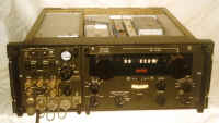
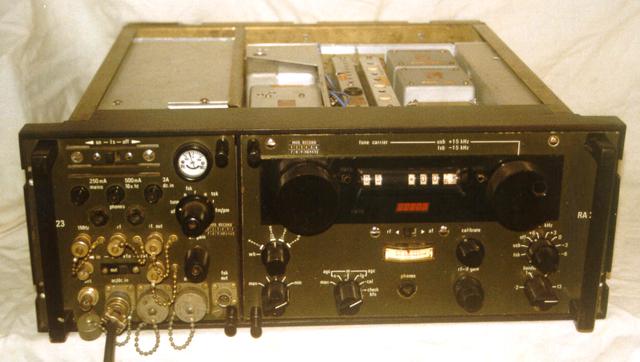 Green RA-217D Radio Receiver |
The photograph shows the green RA-217D on the right with the MA323 on the left in the
19" rack frame. The top cover has been removed. The names are partially hidden by the
black rack handles at the left and right, where only the 23 of the MA323 and only the RA
of the RA-217D is visible. Controls |
It also has lever which locks the knob. The similar large black knob at the top right is the frequency selector that selects the kilohertz and goes from 000 to 999. This does not have click stops, and revolves the digits with a uniform resistance, until the transition from 9 to 0 (when increasing frequency) which clicks over the tens of kilohertz digit. A momentary increase in resistance is felt. These knobs are labelled TUNE and MHz and KHz. The mechanical Speedo type kilohertz display is visible in the right hand window. The display digits, actually go slightly below 000 khz and above 999 khz, to allow some overlap with the adjacent bands. The actual readings are -975 and +025. A "plus" symbol and "minus" symbol is displayed in the centre window, instead of the usual "decimal point". Each kilo hertz is divided into 5 divisions which implies 200 Hz resolution. This knob also has a lever which locks it. It uses a cam to expand a rubber ring inside the knob. Each knob can be locked individually. In the centre is an edge type meter which displays the Signal Strength. It can be also display the Audio Level, when the switch above it is set to AF (usually set to RF). The black on white meter scale is calibrated in dB with 20dB divisions from 1 to 100. The left hand side is labelled 1 uV. There is also a red line between 20db and 40 dB labelled 1 mW, used when the meter is set to AF. Below the meter is a jack labelled PHONES which allows a pair of headphones to be plugged in.
The switch at the right lower corner is labelled BANDWIDTH kHz which selects the different IF bandwidths. It can select 13, 3, 1, or 0.2 kHz bandwidth. The switch above this is labelled BFO kHz which selects the Beat Frequency Oscillator characteristics. It has an OFF position for AM reception. It has a USB and LSB position which select -1.5 kHz for Upper Side Band, and +1.5 kHz for Lower Side Band reception. It has other fixed frequency positions of +6, +3, 0, -3, -6 kHz. In the 0 position, the knob in the centre of this switch can be used to vary the BFO frequency, which is often useful for CW reception. At the bottom right hand side is the RF/IF GAIN control, which controls the gain of the RF and IF amplifiers. Near the centre, on the right hand side is the CALIBRATE knob. When the receiver is tuned to any 100 kHz position on the display, this knob can be used to set the frequency exactly, by listening to the heterodyne with an internal crystal oscillator.
The switch on the lower left hand side labelled AE. ATT. and is used to switch in aerial attenuation (if necessary). When set to MIN, there is no attenuation. When switched to any of the other positions, it introduces 10 dB of attenuation, up to -40 dB in the MAX position. The knob above this is the RF TUNE control which is a preselector (tuneable filter). In the extreme counter clockwise position, labelled WB (wide band), it is switched out. This is a suitable position for tuning across the band. When the desired signal has been tuned in, it can be increased in strength and adjacent signals reduced by tuning the filter. It is labelled in bands, and is very sharp for the higher frequencies (perhaps too sharp). Between the attenuator and the phone jack, is the function switch. It has positions to select the AGC, MAN to turn it off, S for short, M for medium and LG for long. The CAL position turns on the calibrator, and it has another position labelled CHECK BFO.
The MA323 FSK and Terminating unit has a row of connectors across the bottom. These are for the ANT (antenna) input, the power input (labelled AC/DC IN), ANC. for ancillary connections, MHZ DISPLAY for connection to a Panadaptor display (a device to show a panorama of radio signals centred on the receiving frequency), and FSK OUT to connect to a tele-printer. Above this are 5 BNC connectors for access to the various RF signals in the receiver. They are the 2nd VFO IN and 2nd VFO OUT which are used for slaving receivers together. There is also a switch to switch off the 2nd VFO for this purpose. There is the 1 MHz output, RF output and IF output connectors. All the connectors have dust covers and security chains. The unit has a speaker, which has an LS ON/OFF switch and two PHONES jacks.
There are 3 fuses for the power, labelled MAINS 250 mA, 16V HT 500 ma, and DC IN 3A. There is a function switch which selects the type of signal. The first position is labelled OFF which turns off the mains to the receiver, then TUNE which is the normal position. It has two positions for FSK signals, labelled N and R for normal and reverse. It has another two positions for TSK signals, also labelled N and R. It has a last position for FM/PM signals. There is an AF GAIN control for the speaker and PHONES jack. It has a centre reading tuning meter which allows you to accurately tune in a signal. It shows you if you have tuned to either side of the signal. It is calibrated in uA with the 2 extremes labelled 100. The photograph shows that the receiver is tuned slightly to one side of a signal, and this is also evident as the displayed frequency is above the 5 mHz time signal.
The back panel of the green military RA-217 carries two large connectors that are a type D but with mixed RF and DC connections. These are for connection to the adjacent termination unit. There are 2 cable looms that connect to similar connectors on the back of the MA323 terminating unit. Both units slide into the rack to mate with the connectors. All other connections are on the front of the terminating unit.
The centre of the back panel contains the power supply. It is a plug in unit and has 3 different types. The civilian RA-217 has a mains supply with a 240v input cord and a voltage selector switch. There is a mains fuse of 250 ma and an HT fuse of 500 ma. Another type of power supply is similar, but has no input cord as the mains is supplied through the plug in connector, and from the MA323 terminating unit. A third type is similar to this, but also contains an transistorised inverter for DC operation.
 RA-217 Radio Receiver Civilian Version |
Different Models There is another model of the RA-217D which is the civilian model, called the RA-217. It is basically the same, with the most obvious difference being the grey colour scheme rather than the military green. The photograph shows the grey civilian model RA-217. The controls on the civilian RA-217 are similar. The main differences are that all labels are in cycles rather than in hertz. There is an extra knob above the function switch which locks both frequency knobs at once, rather than individually as on the military version. |
It uses brakes that are pressed against the flywheel rims behind the front panel. The RF preselector knob has two wide band positions and no band marking. The function switch has an extra position labelled POWER OFF that activates two micro switches to turn off the mains. The RF/IF gain control has another knob in the centre, which controls the volume of the audio delivered to the PHONES outlet.
The grey civilian RA-217 has individual coax output sockets on the back, as it is intended for stand alone desktop use. On the right hand side (when looking at the back) is a BNC antenna socket. At the top in the centre is a panel with 8 small coaxial connectors, a switch, and a barrier strip. The switch is for switching the 2nd VFO off to allow for slaving of multiple receivers. There is the 2nd VFO output, and a high and low level 2nd VFO input. There is also the 1 Mcs output, and a high and low level input. The other coax sockets are for the panadaptor output and an input for an LF adapter. The barrier strip allows you to connect the LF adapter AGC and HT.
When the MCs knob is turned to 00, the LF adapter is provided with HT and AGC. Normally the receiver has the RF sections disabled with this frequency setting. If you link the terminals, the RA-217 will operate on this band but with reduced sensitivity. However, it is suitable for strong broadcast stations. Link HT to HT, and AGC to AGC. On the left hand side (when looking at the back) is a panel with 4 coax sockets. These are for the IF unit and provide 1.6 mcs IF output, 455kcs IF output, and 1.145 mcs (input and output) for the IF converter. There is a different IF converter available that uses a 100 kcs IF frequency, and its panel has the 100 kcs IF output and 1.5 mcs (input and output) for the converter. There is a barrier strip at the top left hand side (when looking at the back), which provides HT output (-16 volts), AGC for a diversity system using another receiver, a low audio output of 1 mw at 600 ohms, a high audio output of 10 mw at 600 ohms, and the output of the detector.
There is a further version of the RA-217 called the RA1217, which is the same receiver, but repackaged into a flatter and wider 19" rack module. It is 3 units high.
Design
I have referred to frequencies as mcs and kcs, except where the RA-217D controls are
labelled in Mhz and Khz, and where the RA-217 manual refers to module names and connectors
as Mcs and Kcs.
The receiver is constructed on a cast aluminium chassis, with several small modules all interconnected. Each module is on a cast base with a screened cover, and plugs in with a mixed RF/DC type D connector. The photograph shows a view of the bottom, with a module removed and sitting on the top. It also shows the IF unit on the right, the RF unit on the left, and the plug in power supply at the bottom. At the centre right is the 2nd VFO unit with its cover removed. This shows the ceramic tuning capacitor, and the blue coax cables coming from the mixed D connector. In the centre left is a space where the 1 Mcs Amplifier and 37.5 Mcs module fits. The cast chassis, wiring looms, and the connector are visible. The connector is unscrewed and the back is visible. The double module that belongs in this space, is sitting at the left with the cover removed from one of the modules, and the pair is opened for repair. Here is the Top Layout and the Bottom Layout.
The receiver is a triple conversion super heterodyne design with an interesting selection of IF frequencies, oscillator injection, and control, which is often called the "Wadley Loop". This idea was originally conceived by Dr. Trevor Wadley who used it for a stable Wave meter he designed during the 1940s. This receiver is unlike any normal super heterodyne, as the local oscillator is injected twice, at different points, which eliminates any oscillator drift or instability. RACAL have made several receivers using this principle, as have other manufacturers such as Drake, Barlow, and more recently, some Japanese companies.
The theory behind this, is that most oscillator drift and instability occurs in the first converter, so if you can get rid of this, then the receiver will be stable. One way is to use a fixed down converter with crystal control and a tuneable IF frequency. Another way is to design a very stable oscillator. A third way is to cancel out any drift and this is what the Wadley Loop does. It achieves this by mixing the received frequency up to a high IF frequency (40 mcs in this receiver). It uses the SAME oscillator to generate a lower frequency (37.5 mcs in this receiver). These signals are then remixed to generate the second IF frequency. Any drift cancels out!
The back end of the receiver is a conventional super heterodyne with a fixed IF frequency of 1600 kcs, and a variable IF over the range 2 - 3 mcs, tuned using the KHz knob (calibrated 0 to 999 KHz). It is interesting that the manual has the Block Diagram of the RA117. This is the same in most functions but has a few minor differences. The power supply is shown as 200 volts, but is in reality -16 volts. The block called "BAND PASS FILTER 3RD IF" is also connected directly to the "DETECTOR AF AMPLIFIER" block. The Fourth IF is shown as 100 kcs, but this model has a 455 kcs IF . It has no internal connectors or function within the receiver, being for external use only.
The power supply is a modular unit, that can be unplugged from the back. There are at 3 possible power supplies. One uses DC input only in the range 9 - 15 volts or 18 - 30 volts. Another model is a combination AC and DC supply that has 110/240 volt AC input, or 21 - 27 volts DC (positive earth) input and this uses a transistor inverter. I have the conventional Type 408A which is a mains powered 110 or 240 volt supply. This power supply has a power transformer with an external mains cord. The switching is accomplished by two mico switches on the receiver front panel, which uses the 15 pin type D connector to go to and from the power supply. This connector therefore has mains on it! The power transformer has a bridge rectifier and a voltage regulator to provide -16 volts DC to the receiver. This is called the H.T.. (High Tension) throughout the manual. There is also low voltage AC coming from the transformer that is used for the dial lights via a dimmer control, located internally just behind the front panel.
The RF Unit consists of an A.G.C. controller amplifier, 4 filters and an attenuator. It is located on the left hand side of the receiver. The input to the shielded module, is from the aerial terminal and has a fuse and protection diodes, to protect the input from any nearby transmitter. The input is filtered by a 0 - 30 mcs filter to ensure that any high frequencies are rejected. There is an Attenuator which can be used to reduce the level of input signals to prevent overload of the RF amplifier. This is a resistive Attenuator switchable in 10 db steps. It would normally be used in the MIN position. Next is an RF tune control which can be used to peak the desired signal. It consists of 5 tuned circuits that are switched in automatically, depending on which position the Mcs knob is set to. Each coil can then tuned by the control to maximise the signal and reject adjacent ones. If it is turned to one end, the coils are bypassed, and a broad response is achieved, but at a lower gain. This is useful for tuning across the band, and then the desired signal can be peaked. It is basically a Preselector. There are 2 transistors in the RF amplifier each with a low pass filter on their output. The transistors have their gain controlled from the A.G.C. line. There has been a lot of care taken in the design of this receiver front end, to provide protection and filtering.
The output from the RF amplifier connects to the 1st Mixer and 40 Mcs Filter, which is a single module in a long shielded box, located on the top of the receiver. It is a balanced mixer using 2 transistors and a transformer. The 1st VFO input to the mixer, produces a high IF frequency of 40 mcs, which is connected to the passive IF filter. This filter has 8 tuned coils spaced apart, and it is hard to see how the coupling between them occurs! The filter is 1300 kcs wide and centred on 40 mcs. It has sharp sides and the manual has no alignment data, but recommends returning it to the factory for repair.
The 1st VFO is connected to the MHz knob and is located on the left hand side of the receiver next to the RF amplifier. It is a single module containing 3 printed circuit boards. The main board is the oscillator which is a single transistor whose frequency is controlled by a variable capacitor, a high quality component with ceramic insulators. The capacitor is connected to the MHz knob and a mechanical detent, so that is has only 31 positions. These correspond to the 0 to 30 calibrations in the left hand side of the frequency display. The oscillator produces frequencies in the range 40.5 to 69.5 mcs, which are injected into the 1st Mixer to beat with the desired signal to produce to 40 mcs IF frequency. For example, if the desired frequency was 5.100 mcs, the MHz knob would be set to 05 and the injected frequency will be 45.5 mcs. Any signals in the range 5.000 to 6.000 mcs would mix with 45.5 mcs and be converted to 40.500 to 39.500 mcs which will pass through the 1st IF filter. All others will be rejected. The desired frequency of 5.100 mcs will be converted to 40.400 mcs and pass through the IF. The module also contains 2 other printed circuit boards that are buffer amplifiers and have a very similar design. One is used to buffer the signal for the 1st Mixer, the other is used to buffer the signal for use in generating other internal frequencies.
The output from the 1st IF connects to the 2nd Mixer. This is in a module that contains the mixer, the second IF filter and an amplifier for the injection frequency, called the 37.5 Mcs Amplifier. These are all on one printed circuit board and the module is located in the receiver in the centre, at the top, near the back. The mixer is a single transistor with the 40 mcs first IF frequency connected to the base and the 37.5 mcs injection frequency connected to the emitter. The 2 to 3 mcs second IF frequency is extracted from the collector through a band pass filter which consists of 4 tuned circuits in series and 2 tuned circuits in parallel and a tuned circuit in the collector of the mixer. The manual gives a complicated method of tuning these 7 tuned circuits, to ensure a flat pass band and steep sides. I have found that it is easier to use a sweep generator. Any signals from the 1st IF in the range 40.500 to 39.500 mcs will mix with the 37.5 mcs injection and produce signals in the range 3.000 to 2.000 mcs. Continuing the previous example, the desired frequency of 5.100 mcs which appears as 40.400 mcs will be converted to 2.900 mcs and pass through the IF.
The output from the second IF connects to the 3rd Mixer which is a module containing one printed circuit board and located in the receiver in the centre at the top near the middle. The mixer consist of a diode ring with transformer input and output. The second IF signal is low pass filtered to 5 mcs and connected to the transformer input. The 2nd VFO is connected through a band pass filter to a balanced amplifier using 2 transistors, which is connected to the centre taps of the mixer input and output transformers. The difference frequency of 1.6 mcs from the output transformer is connected to a wide band filter consisting of 2 tuned circuits, and then amplified for connection to the third IF amplifier in the IF unit. The 100 kcs calibrator signal is injected into this mixer. This is used for adjusting the KHz dial so that the 100 kcs divisions are set accurately. Continuing the previous example, the desired frequency of 5.100 mcs which appears here as 2.900 mcs will be converted to 1.600 mcs and pass through the IF.
The 2nd VFO has a variable oscillator and 2 wide band buffer amplifiers. It consists of a module containing 2 printed circuit boards and is located on the right hand side of the receiver and underneath. The oscillator covers the frequency range 3.6 to 4.6 mcs and is controlled by the KHz tuning knob which is calibrated from .000 to .999 KHz. The oscillator can be switched off by an external switch, and external input from a synthesiser or the 2nd VFO of a master receiver can be used via the 2nd VFO input connector. The oscillator is a single transistor has a tuned collector circuit with two inductors and the KHz tuning capacitor externally located. One of the inductors in connected to the CALIBRATE control which varies the amount of DC flowing through it and hence provides fine tuning. The oscillator has a regulated DC supply to ensure frequency stability. The buffer amplifiers use 3 transistors and provide 2nd VFO output on the rear panel connector, as well as injection for the 3rd Mixer stage. Continuing the previous example, the desired frequency of 5.100 mcs is selected by setting the KHz knob to .100 to produce the 4.500 mcs injection frequency for the 3rd Mixer. The photograph shows the module with its cover removed, in the receiver.
The IF Unit is a single module containing the audio amplifier, detector, A.G.C. circuit, BFO, 1.6 Mcs IF amplifier, bandwidth filters and output converter. Most of the receiver gain occurs in this module. The third IF amplifier operates at 1.6 mcs and has 4 transistors and 4 tuned circuits and has a gain that is controlled by the A.G.C. level. There are three crystal filters which change the normal 13 kcs bandwidth to narrower bandwidths of 3 kcs, 1 kcs and 0.2 kcs to reduce noise. The A.G.C. Short time constant is inoperative in the two narrowest bandwidth settings. There is a 1.6 mcs IF output signal connected to the back panel.
There is also a converter that produces a 455 kcs output IF signal available on the back panel. These signals are for external use and perform no function in the receiver. It uses an internal 1.145 mcs crystal oscillator for the conversion. An external input of this frequency can be applied if the receiver is to be used with others and a common stable source is a available. The local crystal must be unplugged in this case. Some RA-217 may have a different converter fitted which provides a 100 kcs IF output signal and a 1.5 mcs local oscillator.
The BFO unit has several switch positions which generate different frequencies. It oscillates at 606, 603, 600, 597, and 594 kcs which gives the +6, +3, 0, -3, and -6 kcs difference frequencies. It also has a variable position where it can be continuously tuned around 600 kcs from a front panel control. These are buffered then mixed with a 1 mcs signal to generate the 1.6 mcs BFO frequency. There is a completely separate oscillator for the LSB and USB positions. It has two crystals which are 1.5 kcs above and below the IF frequency, which are 1601.5 and 1598.5 kcs. The BFO signal is amplified and injected into the detector. The manual claims that the BFO is shut off when the CALIBRATE position is selected on the function switch, but this is not the case, the BFO has to be set to the OFF position.
The A.G.C. section has two 1.6 mcs amplifiers which drive the A.G.C. detector. Three different time constants can be selected and the A.G.C. can also be turned off by setting the function switch to MAN. The generated A.G.C. signal is connected to the 1.6 mcs IF amplifier to control the IF gain and also goes to the S meter to show the signal strength. The A.G.C. signal can be adjusted with the RF/IF GAIN control. The A.G.C. signal is available on the rear panel so that an LF unit can be controlled. This same line connects to the RF amplifier. There is a connection to the A.G.C. detector for diversity operation using another receiver.
There are two detectors, one for AM and one for SSB. The AM detector operates only when the BFO switch is in the OFF position, all other positions use the product detector. The detector output is available on the terminal strip on the rear of the receiver.
The audio amplifier is a push pull transformer coupled type, with the output connected to the phone jack on the front and also to the tag strip on the back (labelled 10 mw 600 ohms). The AF GAIN knob controls the volume. There is an independent single transistor amplifier which drives the meter and the output also appears on the tag strip (labelled 1 mw 600 ohms). This amplifier has an internal pre-set control which is intended to drive a Line output.
There are several frequencies that are used in the receiver which are generated in other modules. The 1 Mcs Oscillator, Amplifier, Calibrator, 37.5 Mcs Generator and Amplifier are on a module that has 6 printed circuit boards in a double (or piggy backed) module. This is located at the right hand side underneath the receiver. See the photograph of this module removed from the receiver and open, with the top module cover removed. The top part of this double module contains the 1 Mcs Amplifier, Oscillator and Calibrator. It contains 2 printed circuit boards. The 1 Mcs Oscillator is a single transistor with a 1 Mcs crystal (which can be removed if an external signal is used). The oscillator has 3 buffer amplifiers. One is used to buffer the external 1 mcs input. Another is used to generate the frequency for the variable BFO, to provide the external 1 mcs output, and to drive the Calibrator. The Calibrator has 2 transistors as a regenerative divider driving 2 transformers and 4 diodes as a mixer.
This generates harmonics of 100 kcs, which are injected into the 3rd Mixer to calibrate the KHz dial. The other buffer drives the Harmonic Generator. The bottom part of the double module contains 4 printed circuit boards which are the Harmonic Generator, Mixer, and 37.5 Mcs Filter. The 1 mcs input frequency is applied to a diode that generates harmonics up to and beyond 32 mcs. These are then amplified by a transistor and filtered to remove harmonics above 32 mcs. This output is then applied to the balanced Harmonic Mixer which mixes with the 1st VFO signal. The 1st VFO produces a frequency between 40.5 to 69.5 mcs (in 1 mcs increments) which when mixed with all the harmonics of the 1 Mcs Oscillator produces many frequencies. The Harmonic Mixer has a tuned circuit to select only the 37.5 mcs beat frequency. The 37.5 mcs is then amplified and connected to the 37.5 Mcs Filter module. This a long module located at the top of the receiver and the coils are spaced so far apart that it seems as though it couldn't possibly work!. The manual gives no alignment details other than its centre frequency and bandwidth of 150 kcs. It is required to return this filter for factory alignment. The 37.5 mcs is used for injection in the 2nd Mixer.
 RA-217D Radio Receiver Internal View |
Restoration When I purchased this receiver, I had the choice of two. One was complete and working in the 19" rack frame. The other was low on sensitivity and had the grey civilian receiver in the rack frame. I chose the cheaper grey one, not realising how much trouble I had let myself in for! I removed the grey receiver from the rack frame. The receiver had this constant whistle and hissing noise. It turned out that the audio power amplifier was oscillating and needed a load on the output terminals, so I added a resistor across the output terminals on the back panel. |
I began to chase the low sensitivity problem. Luckily I had the manual, as it turned out to be a long chase. I verified that the frequency tuning worked and that the sensitivity was only 10 micro volts instead of the 1 micro volt that it should be. The IF unit seemed to be working well, as it only needed 10 micro volts to drive it. This meant that the mixers, IF amplifier and RF unit were only giving a gain of unity. The input to the first IF was 1.6 mcs, which was easy to generate and measure. The first IF was 40 mcs which made things a little more difficult. Once the covers were off the units, signal injection and measuring, gave inconsistent results, often because the measuring attempt loaded the circuit or connecting the earth braid upset things. I eventually decided that the RF unit was to blame (but I was not 100% sure).
This receiver is full of filters! The RF unit alone has four. I bypassed the first two, and fed the signal directly to the RF amplifier. This showed no change and so eliminated these two filters as the problem. I removed the RF unit so that I could work on it. The gain of the RF amplifier is varied by the amount of capacitor bypassing on the emitters. This is controlled using a transistor and a diode matrix fed from the A.G.C. line. I varied the A.G.C. voltage to verify that this was working properly, and also disconnected the capacitors to remove the effect entirely.
This made no improvement. I changed the transistors, and checked all the resistors and capacitors. There are two low pass filters, one after each amplifier. They seemed to be working OK although the first one seemed not quite right. The individual components were checked. All seemed OK. Each filter has 2 series inductors and several capacitors to earth. I noticed that each also had a 33 ohm resistor to earth at the input and output of the filter. I disconnected these to see if the gain increased, but the reverse happened. I couldn't find 3R13 which is at the end of the first filter. The printed circuit board layout had a position where it should be, but it was vacant.
The tracks underneath had never been soldered! I soldered a 33 ohm resistor in, thinking it was a waste of time as it would load the signal, not help it. The sensitivity suddenly came up to normal, as it should be. It appears that the resistor is needed to terminate the filter, to make it work correctly. Since this RF unit has never had the resistor fitted, I can only conclude it has had this factory fault since new.
I put the receiver back together and left it running while I did other things. After an hour it stopped! I started looking for the fault and it began working again. It kept on starting and stopping for no reason that I could determine, so I gave up after a few days. It had taken me a couple of weeks to track down the RF fault! I put all the parts in a box and went onto another project.
Six months later, I put the receiver back on the bench and began chasing it again. The RF wasn't completely dead, but was very poor sensitivity. I checked the previous fix, but it was unrelated to that. The KHz tuning was very very mushy, so I began looking in the mixers. Once again a problem arose of how to measure RF levels and frequency and how to inject signals without affecting the circuit. A spare set of modules, so that I could perform module substitution would have made the fault location trivial. In the absence of these, I had to fault find in the traditional way.
After a large amount of trial and error, I decided that the RF chain was probably working and that the injection of frequencies into the mixers was suspect. The generation of the injection frequencies is not normal in any stretch of the imagination. In addition to this was the extensive use of filters. There are two strange filters in this receiver, as most of the others are fairly conventional. These two are on individual cast aluminium bases and are 6 inches long and 1 inch wide and high. They are visible in the photographs of the front views of both versions. They are passive LC filters and set up as broad band filters, one at 40 mcs for the first IF and the other at 37.5 mcs for the injection frequency. The manual says don't touch them, and return them to the factory for alignment. They are a long printed circuit board with seven (eight on the 40 mcs filter) tuned circuits with no electrical connection between them as they rely on inductive coupling. By this time I had obtained a box of parts from a wrecked RA-217 so I substituted the filters but it made no difference. Unfortunately there was not a complete set of modules. I began looking in the frequency generation chain for the problem, attacking it from both ends (refer to the block diagram). The 1 Mcs Oscillator was working, and the output filter was substituted. several of the blocks were small printed circuit boards in side a common can. One module had two cans piggybacked on each other! The top module has two printed circuit boards inside the can which are the 1 Mcs Oscillator and Calibrator board, and the other is the 1 Mcs Amplifier board. The lower module has 4 printed circuit boards inside it which are the Harmonic Generator, Harmonic Filter, Harmonic Mixer, and 37.5 Mcs Amplifier boards.
These modules have to be removed to work on them, and it appeared as though the fault was here somewhere. Banging and crashing, heating and cooling, powering it up and down, couldn't make the fault appear, but it would still stop when it felt like it, and often start when I touched a probe somewhere, and it didn't seem to matter where! I injected signals into the 37.5 Mcs Amplifier and mixer at several places and looked at the output with an oscilloscope and a wide band level meter, and it appeared as though the amplifier and mixer was working. I injected 1 mcs into the Harmonic Generator and the strange looking output signals seemed to indicate that this was functioning too. I decided that there was no 1 mcs signal getting here even though the oscillator was working.
This pointed to only 1 transistor in the 1 Mcs Amplifier and shaper, although there were several others involved in provision for external input and output of the 1 mcs and also coupling to the Calibrator. The board is visible in the photograph of the module sitting on the receiver. It is the board with one IF can, on the top layer of the double module at the top of the photo. Replacing the transistor didn't fix it. I checked all the resistors, checked the IF can with a Grid Dip Oscillator, checked the capacitors and a bridge, all to no avail. I was looking at the board, knowing the fault was there but I couldn't see it. I decided to look at it through a magnifying glass, for cracks in the traces. The clearance on the underside is small as it is mounted on the cast base, so I was moving things around to examine all the traces, when I noticed that the coax cables terminated under there, were a little messy. Looking very closely I could see whiskers from the braid sticking out and one was touching a track. I did not disturb this, but put the module back in, and began to move the coax around. It didn't but make the fault go away. I actually pushed an insulator between the trace and the coax and it started working. I re-terminated the coax and insulated the braid. I put it on the bench and let it run for a few weeks but the fault did not return.
The MHz knob actually tuned from 0 to 32 which seemed strange. There was no gain above 30 Mhz anyway. I examined the knob stops and noticed that the stop tags were on the outside of the stops rather than the inside. This can easily be done when the knob and shaft are loosened or removed. I repositioned them.
I decided to do an alignment, which is not a simple task. I had done some modules while looking for the fault, thinking that following the manual would ensure that the modules were functioning properly, and help me eliminate the good ones. I borrowed a sweep generator for the higher filters as my sweeper only went to 30 mcs. I substituted what duplicate modules I had and if there was no change, I bypassed that one. I followed Chapter 4 in the manual which has the alignment procedure. The IF module was straightforward. The 3rd Mixer has a strange procedure that says tune one coil at this frequency for a max, tune another one at a another frequency for a min, do a few more then check it for flatness, if not flat then do it again. I got fed up with this and fired up the sweep generator. I could see the pass band and as I tuned a coil, I could see the effect. It took 2 minutes to get it flat and in the pass band. The sweeper made the 2nd Mixer simple as well. It was bit tricky to get the strange harmonically rich wave forms in the 37.5 Mcs Generator to their correct shape. The VFOs and 1st Mixer were OK and I had already done the RF unit.
I now had a working RA-217, but grey in colour, with a green rack and FSK module. So I had a choice as to put it back together this way, or make a cover for the grey RA-217 and use it like this, or add the green parts and put it together as the green receiver.
In the box of parts was the green front panel, knobs and connectors. So I decided to make it into the military version, reasoning that there was little electrical difference, mainly cosmetic. Changing the front panel, meant that I had to remove the lock knob and mechanism and use the individual knob locks. I was short one tuning knob and one other knob so I painted two of the grey ones. The power on/off switch is on the FSK unit, so I removed the function switch and reset the switch stop, so that it would not rotate to activate the micro switch. The RF/AF GAIN control is a double knob on concentric shafts on the civilian version, and since the military version has a gain control on the FSK unit, it only has an RF GAIN control here. I left this as it was because the AF gain control affects the headphones jack on the front panel and the control on the FSK unit affects the phone jacks and speaker on this unit. They do not interact. The Preselector has a Wide band position on only one side of the control in the military version, but both sides in the civilian version, but I did not change this. That was the extent of the cosmetic front panel differences.
I made up the brackets so that the FSK unit could plug in and mate with the contacts. Since the civilian version had individual terminals and coax connectors on the rear panel, I had to trace out the circuit and connect them as appropriate. The connectors are mounted to the base plate and individual cables connect to the back of the receiver. The mains cord was removed from the power supply and wires connected to the internal terminals and the connector. I had to make up 2 black posts that hold the receiver in place. Upon digging through my box of connectors, I found the mains connector and made up a cable for the FSK unit.
Conclusion
The RA-329 is a nice receiver to use and it is very sensitive. It has very easy and clear
tuning, a good BFO and kcs resolution that makes SSB reception simple. The built in FSK
unit and meter make TTY reception painless. It suffers from high internal noise, fiddly
preselector tuning, and is exceedingly complicated inside. The use of individual modules
make repair easy, if you have a spare set of modules!
References
RA-217 H.F. Communications Receiver Volume 2 Maintenance Manual, Ref 201 Issue 1 -
4.67.400, RACAL COMMUNICATIONS LIMITED, BRACKNELL, BERKSHIRE, ENGLAND.
Visitors to this page since 20 February 2000
Back to Your Articles Index Page.
Army Radio Sales Co. Home Page.