10) Required Parts
Items necessary for the installation of Radio Set SCR-284-( ) in Truck, 1/4-ton, 4 x 4,are listed below:
| Quantity | Stock No. | Item |
| 1 | 2Z502 | Bag BG-102, for spare parts, batteries and headsets. |
| 1 | 2Z529 | Bag BG-102, for Power Unit PE-103-( ). |
| 1 | 2Z1131 | Box BX-31. for spare vibrator and tubes. |
| 2 | 2Z2651-421 | Clamp AIC-421, including spare. |
| 2 | 2Z2651-422 | Clamp AIC-422, including spare |
| 2 | 2Z2651-423 | Clamp AIC-423, including spare. |
| 2 | 2Z2651-424 | Clamp AIC-424, including spare. |
| 1 | 3E1501 | Cord CD-501. |
| 3 | 3E1307-5.5 | Cord CD-307-A, including spare. |
| 1 | 3E1318 | Cord CD-318. |
| 3 | 3E1604 | Cord CD-604, including spare. |
| 1 | 2Z3367 | Cover BG-67-( ), for mast base. |
| 1 | 2Z3400-154 | Cover BG-154, for radio set. |
| 1 | 2Z4641 | Frame FM-41. |
| 1 | 6L50-284V26 | Hardware bag. |
| 3 | 2B830 | Headset HS-30, including spare. |
| 1 | 3G586 | Insulator IN-86, for tying down mast sectiont. |
| **4 | 3G604 | Insulator IN-104, including spare. |
| 1 | 3Z3445 | Key J-45. |
| 1 | 3Z3448 | Key J-48, including cord, plug, and cover. |
| 1 | 2Z6310-7 | Loudspeaker LS-7. |
| 1 | 2A2088-57 | Mast Base MP-57. |
| a1 | 2A2090-45 | Mast Base Bracket MP-45. |
| 2 | 2A2349 | Mast Section MS-49, including spare. |
| 2 | 2A2350 | Mast Section MS-50 including spare. |
| 2 | 2A2351 | Mast Section MS-51, including spare. |
| 2 | 2A2352 | Mast Section MS-52, including spare. |
| 2 | 2A2353 | Mast, Section MS-53, including spare. |
| 2 | 2B1567 | Microphone Cover M-367. |
| 1 | 2B1617 | Microphone T-17. |
| 1 | 2B1645 | Microphosbe T-45. |
| 1 | 3H4600-104 | Power Converter Unit PE-104-( ), including spare vibrator. |
| 1 | 3H4600-103 | Power Unit PE-103-( ). |
| 1 | 2C5374 | Radio Receiver and Transmitter BC-654-( ). |
| 2 | 6Z8371-5 | Reinforcement. |
| 1 | 2Z8O58 | Roll BG-58, for mast sections. |
| 15 ft | 6Z7926 | Rope RP-5, for tying down mast sections. |
| 2 | 6D13051 | TM-275, for Radio Set SCR-284-( ). |
| 10 ft | 1B142 | Wire W-142. |
| **When installation is made for airborne use, delete Mast Base Bracket MP-45 and add the following: 1* Mast Base Bracket MP-50, 2* Insulator IN-104, 2* screw, hex. head 5/16"-24 x 1 1/2" long, 2* screw hex, head, 3/16"-24 x 1" long, 4* nut, hex, 5/16"-24, 8* Shake proof washer, 5/16" I. E. T., 1 terminal. | ||
Assembly and Installation
a.) Preliminary Modifications.
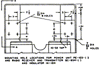
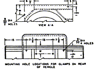
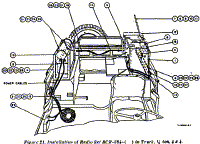
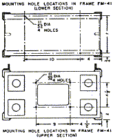
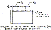
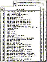
Before proceeding with installation, perform all necessary drilling of vehicle, and cutFrame FM-41 into two sections, as shown in figure 21. Discard pieces cut from the uprightframe members.
b.) Procedure.
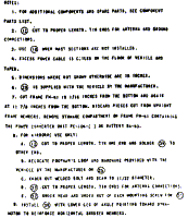
Components of the radio set should he installed as shown in figure 21 and as directedbelow:
Part and Location | Method and Materials |
| Reinforcement (item 36, flg. 21). | Drill holes in the channels holding rubber snubber blocks, for the dynamotor on lower half of Frame FM-41. Secure two reinforcements to the channels with hardware, provided, as shown in figure. 21. |
| Frame FM-41 (item 4, figure 21), on wheelwells. | Secure lower section of Frame FM-41 to right wheelwell with hardware provided. Secure upper section of Frame FM-41 to left wheelwell with hardware provided. |
| Power Unit PE-103-( ) (item 2, figure 21), on lower section of Frame FM-41. | Open spring cover in base of Power Unit PE-103 ( ) and set the slotted voltage-adjustment screw for 6-VOLT OPERATION as marked. Set the three circuit breakers to ON, position. Place power on lower section of Frame FM-41 and secure with provided wingnuts. Route power cords to car terminal box and secure with clamp No. 10, as shown in figure 21. |
| Radio Receiver and Transniitter BC-654-( ) and Power Converter Unit PE-104-( ) (items 1 and 3, figure 21), on upper section of Frame FM-41. | Check units with serial numbers below 12,000 to see that modification per MWO SIG 11-275-4 has been performed. The voltage-adjusting screw on Power Converter Unit PE-104-( ) must be set for 6-VOLT OPERATION. If power converter unit is not already installed, open the small door of the power supply compartment of Radio Receiver and Transmitter BC-654-( ), pull out the plug, slide power converter forward, and set the voltage adjusting screw for 6-VOLTS as marked. Place radio receiver and transmitter on upper section of Frame FM-41l as shown in figure 21, and secure in place with spring fasteners provided. Warning: If vehicle is equipped with 12-volt conversion adjust Power Unit PE-103( ) and Power Converter Unit PE-104-( ) to 12 volts. |
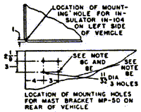
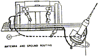
| Insulators IN-104 (item 13, figure 21). | Attach one Insulator IN-104 to top of driver's seat and two Insulators IN-104 to top left edge of vehicle as shown in figure 21, Antenna and Ground Routing. For airborne use, install two extra Insulators IN-104, one on Mast Base Bracket MP-50 and one on left rear corner of vehicle as shown in figure 21, Antenna Location for Airborne Use. |
| Clips (item 16, figure 21). | Secure clips, provided in hardware bag, to rear of vehicle with screws, nuts, and lockwashers supplied, as shown in figure 21. |
| Cord CD-601 (item 14, figure 21). | Use only rubber-jacket cord. Connect Cord CD-501 to Power Unit PE-103-( ) and to Radio Receiver and Transmitter BC-654-( ). |
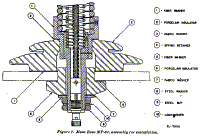
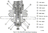
| Mast Base Bracket MP-45 and Mast Base MP-57 (items 5 and 6, figure 21), on upper rear of vehicle. | For standard installation, clamp Mast Base Bracket MP-45 on upper rear of vehicle, left side. as shown in figure 21. Assemble Mast Base MP-57 on Mast Base Bracket MP-45 as shown in figure 8. Use Wire W-142 for antenna and ground connections, as shown in figure 21. Strip insulation from about 1/2 inch of each end, solder-tin. one end, and solder terminal to other end. If Mast Base MP-37 is supplied, see figure 7 for assembly instructions. |
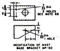
| Mast Base Bracket MP-50 (item 35, figure 21), for airborne use only. | When installation is made for airborne use, see figure 21, Antenna Location for Airborne Use. Drill indicated holes in vehicle for mast base bracket, and drill indicated holes in Mast Base Bracket MP-50 for footman loop as shown. Remove the footman loop f rom rear of vehicle, and secure mast base bracket. Secure mast base bracket on rear of the vehicle with hardware provided. Cut a 68-inch length of Wire W-142, strip insulation from about 1/2 inch of each end, and solder-tin the tips for antenna connections. Route and connect antenna and ground leads as shown in figure 21, Antenna Location for Airborne Use. |
| Mast Sections MS-49 through MS-53 and Clamps MC-421 thriugh MC-424 (items 7 through 11, figure 21), Cover BG-67-( ) (item 18, figure21). | Screw mast sections together. Place clamps over joints, and screw mast section into mast base. When removed. stow mast sections in Roll BG-58. Place Cover BG-67-( ) over mast base when mast sections are not in use. |
Back to Installation of Radio Equipment in Truck, 1/4-Ton, 4 x4 Index Page.
Army Radio Sales Co. Home Page.
