22 Assembly and Installation
a.) Truck, 1/4-Ton, 4 x 4. Components of Radio Set SCR-499-( ) should be
installed in Truck, 1/4-ton, 4 x 4, as shown in figure 36 and as directed below:
Part and Location |
Method and Materials |
| Mast Base Bracket IP-59-A, on rear of vehicle, left side. | Attach to rear of vehicle with hardware provided and shakeproof washers, as shown in figure 36. |
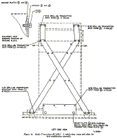
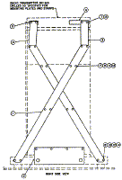
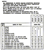
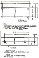
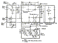
| Radio Transmitter BC-610-( ), in rear of vehicle, center. | Refer to figure 36. Remove transmitter from its shock mounting. Remove bottom plate, from right side of shock mount. Drill holes in bottom plate, as shown in detail 2, figure 39. Secute bottom plate to vehicle with two 1/2"-13 x 2" screws, using eight flat washers as spacers, on each bolt, between plate and vehicle floor. Assemble shock mount in place in vehicle, and mark for drilling of holes in brackets (detail 5, figure 38) for left side of shock mount. Remove shock mount from vehicle, and drill required 17/32" holes in brackets. Fasten shock mount to transmitter. Place transmitter and shock mount in vehicle as shown in figure 36. Remove handles from sides of transmitter. |
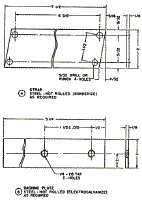
| Shock mounting for Antenna Tuning Unit BC-939-( ), on top of left wheel well. | Refer to figure 40. Insert a 1/4"-20 x 1 1/2" screw with lockwasher upward through each shock mount, item 5. Secure one shock mount on each end of brackets, item 4 (detail 7,. figure 38), by securing screws in tapped holes in bracket. Assemble these four shock mounts on two mounting brackets, item 3 (detail 6. figure 38) using sixteen No. 10-32 x 3/4" screws, and nuts and lockwashers provided. Insert two 5/16"-24 x 1 1/4" screws upward through top of wheel well from underneath and two screws through cover of compartment at rear of wheel well, using two reinforcing plates, items 7 and 8 (details 3 and 4, figure 38), on under side. Secure screws in place with hex. nuts on upper side. Place assembled shock mounting brackets shown in plan view of figure 40, over screws and secure brackets with nuts and lockwashers. |
| Antenna Tuning Unit BC-939-( ), on shock mounting bracket. | Place tuning unit on shock mounting bracket and secure with wing nuts and lockwashers as shown in figure 36. |
| Mast Base MP-47-A and bonding jumpers, on Mast Base Bracket MP-59-A. | Install Mast Base MP-47-A on Mast Base Bracket MP-59-A with six 3/8"-16 x 1" screws, nuts, insulator gaskets, and shakeproof washers (one shakeproof washer under each nut and one under each screw head). Attach a 3/8" x 8" bonding jumper to screw on mast base ring nearest vehicle. Attach this bonding jumper from Mast Base MP-47-A and a 3/4" x 10" bonding jumper from shock mount of Antenna Tuning Unit BC-939-( ) to a 1/4" stud in rear of vehicle with 1/4" hex. nut and three shakeproof washers (one under nut, one between bonding jwnpers, and one next to vehicle). |
| Mast Base MP-22, on cowl, right side of vehicle. | Secure to cowl with four 5/16"-24 x 1" screws, nuts, and lockwashers, as shown in figure 36. |
| Platform (item 2, figure 38) and Mounting FT-162, on floor of vehicle, right side, forward of right rear wheel. | Attach Mounting FT-162 to platform with hardware provided, using shakeproof washers, and attach platform to floor and wheel well with hardware provided, using shakeproof washers as shown in figure 36. |
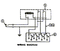
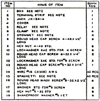
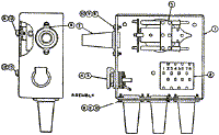
| Radio Receiver BC-342-( ) and Cover BG-75-A. | Remove receiver chassis from cabinet. Remove small angle brackets, part of Mounting FT-178, from top of cabinet. Drill left end of cabinet as shown in figure 39. Place Cover BG-75-A over the cabinet. Place relay control box on left side of receiver cabinet (with open side against cover and cabinet) and secure with three No. 8-32 x 2 1/2" roundhead machine screws, and nuts and lockwasers provided, as shown in detail 12, figure 39. If a complete relay control box is not at hand, assemble and wire as shown in figure 39. Connect external leads from relay, control box to radio set as shown in detail 6, figure 39. Replace one small angle bracket on top right front corner of cabinet. (The other angle bracket is not used for this installation.) Replace receiver chassis in cabinet and place receiver on Mounting FT-162. Secure in place with snap slide fasteners provided. |
| Wire W-128. | Connect Wire W-128 from relay control box to Mast Base MP-42, to ammeter on dashboard of vehicle, to right side of Radio Transmitter BC-610-( ), and to Mounting FT-162, as shown in figure 36. |
| Mounting FT-178 | Secure mounting to right side of vehicle above Radio Receiver BC-342-( ) with hardware provided, as shown in figure 36. Bend threaded rod of mounting to fit and couple to small angle bracket on top right corner of radio receiver with wingnut provided. |
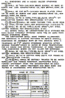
| Chest CHA (small section), Box BX-19-A, and turnbuckle assemblies, on right wheel well. (See figure 36.) | Drill holes in Box BX-19-A as shown in detail 9, figure 39. Use Box BX-19-A as a template and drill holes for mounting on small chest. Attach Box BX-19-A to rear of chest with screws, nuts, and washers provided. Attach twin tumbuckle assembly on right side of vehicle and attach single turnbuckle assembly on left side of right wheel well, for holding down chest. Place chest on wheel well and secure in place with tumbucldes provided. See chart (detail 11, figure 38) on door of chest and stow spare parts in chest as shown on chart. |
| Mast Sections MS-49 through MS-53, Clamps MC-421 through MC-424, and anticorona ball (for Radio Transrnitter BC-610-( )). | One each Mast Sections MS-49 through MS-52 and three Mast Sections MS-53 are required for this installation. Screw mast sections together. Secure joints with mast clamps. Install anticorona ball on Mast Section MS-49 and screw assembled sections into Mast Base MP-47-A. When mast sections are removed, place cover (item 3, figure 44) over mast base and place mast sections in Roll BG-( ). |
| Mast Seations MS-49 through MS-51 (for Radio Receiver BC-342-( )). | Screw mast sections together. Screw assembled sections into Mast Base MP-22. Place mast sections in Roll BG-( ) when not in use. |
| Coaxial Cable, RD-8/U (detail 3, figure 39) and shield bracket (detail 1, figure 38). | Make up coaxial cable assembly as directed in detail 3, figure 39. Solder No.1 clamp to shielding and to inner conductor. Cut shielding back far enough from tips to prevent shorting to clamp on inner conductor. Attach one end of coaxial cable to terminal posts on Radio Transmitter BC-610-( ) and other end to terminal posts on Antenna Tuning Unit BC-939-( ) with wingnuts and lockwashers provided, as shown in figure 36. Secure shield bracket over terminal posts on transmitter with screws, nuts, and lockwashers provided. Secure coaxial cable to transmitter with No. 5 clamp as shown in detail 1, figure 39. |
| Wire W-28. | Refer to figure 36 and detail 5, figure 39. Solder terminal lug for No. 10 screw to end of Wire W-28. Tighten one of the setscrews on lower portion of Mast Base MP-47-A until it is in as far as possible. Attach lug to stem of Mast Base MP-47-A with a No. 10-32 x 1/2" screw and two No. 10 shakeproof washers, inserting screw in setscrew hole. Attach other end of wire to binding post on rear of Antenna Tuning Unit BC-939-( ). |
| Outlet box, BX connectors, duplex receptacle, Cord CD-763. | Prepare a 48-inch length of Cord CO-141. Secure outlet box to left side of right rear wheel well with screws provided. (See figure 40.) Install receptacle in outlet box. Remove female plug from Cord CD-763 and attach plug to prepared cordage. Install two BX connectors through appropriate knock-out holes in outlet box. Insert plug on end of 48-inch length of Cordage CO-141 into receptacle on transmitter. Connect other end to outlet box as shown in figure 36. |
| Cord CD-564. | Connect Radio Receiver BC-342-( ) to receptacle outlet box with Cord CD-564. |
| Power Unit PE-75-( ), on front bumper of vehicle. | Secure power unit to front bumper with four 5/16" screws, nuts, and shakeproof washers, as shown in figure 36. Connect Cord CD-763 between power unit and outlet box. Remove tool box from top of generator and stow contents of tool box in modified Chest CH-88-A in truck. Discard tool box. |
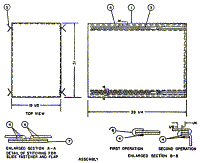
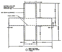
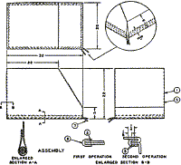
| Covers. (See figure 44.) | Place cover (item 1) over Power Unit PE-75-( ) on front bumper of truck. Place cover (item 2) over chest on right side oi truck. Place cover (item 3) over Mast Base MP-47-A. |
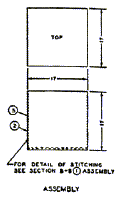
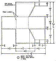
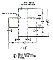
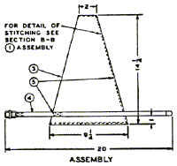
| Covers. (See figure 43.) | Place cover (item 1) over Radio Transmitter BC-610-( ), if desired, transmitter may be operated with cover in place by opening zippers. Place cover (itern-2) over Antenna Tuning Unit BC-939-( ). Remove antenna lead from tuning unit while cover is in place. Cover must be removed when operating radio set. |
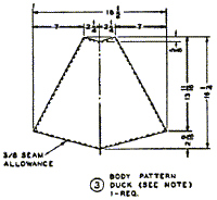
| Canvas top for truck. | Install footman's loop on sides of truck as shown in figure 40. Drill holes in Mast Base Bracket MP-59-A as indicated in plan view and install studs, item 10, for fasteners. Place canvas top over truck, close zippers, and secure straps to footman's loops. End of canvas top having four straps is rear of canvas top. Radio set may be operated with canvas top in place. |
| Insulator IN/121, chain and snap buckle (items 23 and 24, figure 36). | Use to insulate antenna lead-in through canvas top. Attach snap buckle to one end of chain. Load truck heavily to depress springs and use chain to snub truck frame to rear axle to reduce height for loading into cargo plant. (See figure 36.) Draw chain tight, pass one of the end links through a link on other end of chain, and secure with snap buckle. |
| Stowage of items in truck. | Stow items not carried in spare parts chest as follows: Stow tube (flexible nozzle) and trouble lamp in map compartment. Stow Counterpoise CP-15 (not required in this installation) in compartment at right rear of vehicle. Stow Roll BG-56-( ) and Antenna Assembly RC-293 on floor of vehicle, right side, at rear of transmitter. Place 5-gallon gasoline drum in holder on rear of vehicle. |
b.) Trailer Bantam
Components of Radio Set SCR-499-( ) should he installed in trailer, bantam, as shown in
figure 37 and as directed below:
Part and Location |
Method and Materials |
| Power Unit PE-75-( ), brackets and U-bolts (item 9, figure 38). | Place Power Unit PE-75-( ) on floor of trailer, center. Secure power unit to frame members of trailer with brackets, U-bolts, wingnuts, and washers, inserting U-bolts upward from underneath triler as shown in detail of figure 37. |
| Chest (large section cut from Chest CH-88-A). | Attach one hook (item 14, figure 37) on inside of right panel, and one hook on inside of left panel of trailer for attaching turnbuck assemblies on chest. Attach hook fasteners to rear panel of trailer using hardwood blocks as spacers (view B-B, figure 37). Fasten latch bracket, item 16, as shown in view B-B, figure 37. Piace chest in rear of trailer and secure in place with anchor fasteners (item 17), snap hooks, item 15, and turnbuckle assemblies. Stow spare parts in chest as indicated on chart of contents (detail 10 figure 38) on door of chest. |
| Chest CH-77 (or Tool Equipment TE-48). | If Tool Equipment TE is supplied with equipment, secure to floor of trailer, right side, with straps provided. If Tool Equipment TE-48 is not supplied, secure Chest CH-77 in trailer, and remove necessary tools, tape, wire, flashlight, etc., from Chest CH-88-A and place in Chest CH-77. |
| Fire extinguisher and holder. | Secure holder to left side of panel and floor of trailer. Use a 1/4" flathead screw through side panel and two 5/16" flathead screws through floor. |
| Frequency Meter Set SCR-211-( ). | Secure in left front corner of trailer with straps provided. |
| Roll BG-56-( ). | Stow spare mast sections in Roll BG-56-( ) and secure roll to flange of right panel of trailer with straps provided. |
| Brackets for 5-gallon gasoline drums. | Place one bracket in right front corner of trailer and two brackets back to back in front of trailer. Secure brackets to floor with 5/16"-24 x 1" screws, and nuts and lockwashers. Use 1/4"-20 x 3/4" screws, nuts, and lockwashers to secure backs of brackets together. Place gasoline drums in brackets. |
| Tube, flexible nozzle, and clips. | Fasten clips (one above the other) on right panel of trailer near gasoline drum holder and filler. Place tube in clips. |
| Note. Disposition of components of Radio Set SCR-499-( ) not required for this installation is left to discretion of using organization. | |
Back to Installation of Radio Equipment in Truck, 1/4-Ton, 4 x 4 Index Page.
Army Radio Sales Co. Home Page.
