20 Required Parts.
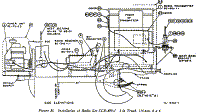
a.) Items necessary for installation of Radio Set SCR-499-( ) in Truck, 1/4-ton, 4 x 4 are listed below:
Quantity |
Stock No. | Item |
| 4 | 2A315 | Anticorona ball. |
| 1 | 2C527-939 | Antenna Tuning Unit BC-939-( ) including 1 Capacitor CA-423, 1 capacitor, vacuum, 12-mmf. |
| 10 feet | Braid, copper, strand for ground lead. | |
| *1 | 2Z1119 | Box BX-19-A may be removed from Chest CH-121-( ). |
| 2 | 6Z6815-13 | Bulb, 50-watt, 115-volt, for trouble lamp. |
| 1 | 2Z2588 | Chest CH-88-( ). |
| 1 | 2Z2599-121 | Chest CH-121-( ). |
| 2 | 2Z2651-421 | Clamp MC-421. |
| 2 | 2Z2651-422 | Clamp MC-422. |
| 2 | 2Z2651-423 | Clamp MC-423. |
| 1 | 2Z2651-424 | Clamp MC-424. |
| 2 | 3E1201 | Cord CD-201, for Key J-37. |
| 1 | 3E1564 | Cord CD-564. |
| 2 | 3E1605 | Cord CD-605, 78", for Headset HS-30-( ). |
| 2 | 3E1763 | Cord CD-763. |
| 4 | 6Z3654 | Drum, gasoline, 5-gallon. |
| 1 | 6Z3787 | Extinguisher, fire, 4-1b. size, with holder. |
| 1 | 2C1411 | Frequency Meter Set SCR-211-( ), with TM-11-300. |
| *2 | Gasket. insulator, for Mast Base MP-47-A (remove from spare Mast Base MP-47-A). | |
| 1 | 3Z3437 | Key J-37 (spare). |
| 1 | 3Z3445 | Key J-45. |
| 2 | 6Z6815-13 | Lamp, trouble, 115-volt. |
| 1 | 2A2088-17 | Mast Base MP-47-A. |
| 1 | 2A2090-59 | Mast Base Bracket MP-59-A. |
| 4 | 2A2349 | Mast Section MS-49. |
| 4 | 2A2350 | Mast Section MS-50. |
| 4 | 2A2351 | Mast Section MS-51. |
| 2 | 2A2352 | Mast Section MS-52. |
| 6 | 2A2353 | Mast Section MS-53. |
| *1 | Mounting FT-162 (one may be removed from Chest CH-121-( )). | |
| *1 | 2Z6718 | Mounting FT-178 (one may be removed from Chest CH-121-( )). |
| 1 | 2C4342 | Radio Receiver BC-342-( ), including TM-11850, two Lamps LM-27 (spare), one set of tubes installed, and one set of spare tubes. |
| 1 | 2C6500 | Radio Transinitter BC-610-( ), including shock mounting, tuning units, spare fuses and lamps, one set of tubes installed, and one set of spare tubes. |
| 50 feet | 6Z7926 | Rope RP-5, for tying down mast sections. |
| 2 | Stake GP-8, for fastening Rope RP-5 in ground. | |
| 2 | 6Z3654/1 | Tube, flexible nozzle, for 5-gallon drum. |
| 1 roll | 6N8692 | Tape, rubber, 1/2". |
| 100 feet | Wire, antenna. No. 12 gauge, enamel, stranded. | |
| 3 feet | 1A28 | Wire,W-28. |
| *These items are not required if complete Installation Kit MC-549 is available. | ||
b.) Items contained in Installation Kit MC-549 are listed below:
Quantity |
Stock No. | Item |
| 1 | Antenna Assembly RC-293, including 2 telescoping aluminum masts (extended length 25 feet), and 2-guy assemblies, with stakes and polystyrene insulator attached. | |
| 300 feet | 1A148 | Wire W-148, on spool. |
| 1 | 6R36026 | Tape, steel, measuring. 100-foot. |
| 1 | Bag BG-193 for storage of Antenna Assembly RC-293. | |
| 1 | Bonding jumper, 10". | |
| 2 | Bonding jumper, 8". | |
| 3 | 6J952/B10 | Bracket (5-gal container). for drum, inflammable liquid. |
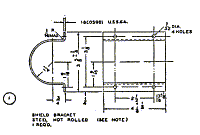
| 1 | Bracket. shield, for insulator protection on Radio Transmitter BC-610-( ). | |
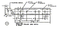
| 2 | Bracket, for mounting Radio Transmitter BC-610-( ). | |
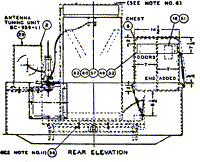
| 2 | Bracket, for mounting Antenna Tuning Unit BC-939-( ). | |
| 4 | Bracket, for mounting Power Unit PE-75-( ) in trailer. | |
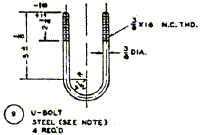
| 4 | Bolt (U-type), for mounting Power Unit PE-75-( ) in trailer. | |
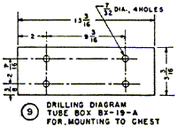
| 1 | 2Z1119 | Box BX-19-A, for receiver spare tubes. |
| 2 | Block, wood, 3/4" x 2" x 5" (any available hardwood). | |
| 5 feet | lF425-8 | Coaxial Cable RD-8/U |
| 1 | Chain, 6". | |
| 2 | Chain, 30". length, size 5/0, 1/4" stock, 7 links per foot electric welded, polished. | |
| 2 | Chest end, plywood, 12 1/8" x 17" x 1/2", for stowage chest. | |
| 1 | 6Q19095 | Chest CH-77, for tool equipment. |
| 1 | Chart, contents (plastic), for stowage chest in trailer. | |
| 1 | Chart, contents (plastic), for stowage chest in vehicle. | |
| 1 | 2Z3375 | Cover BG-75-A, for Radio Receiver B2-( ). |
| 10 feet | 3E-2141 | Cord CO-141, power cord for BC-610-( ), includes spare length. |
| 1 | Cover, for Radio Transmitter BC-610-( ). | |
| 1 | Cover, for Antenna Tuning Unit BC-939-( ). | |
| 1 | Cover, for Mast Base MP-47-A. | |
| 1 | Cover, for Power Unit PE-75-( ) in vehicle. | |
| 1 | Cover, for stowage chest in vehicle. | |
| 2 | Conncctor (BX-type), for outlet box. | |
| 4 | Corner reinforcement, for stowage chests,.No. 67A116-B Hallicrafters Co., or equal. | |
| 4 | Corner reinforcement, for stowage chests, No. 67A113-A Hallicrafters Co., or equal. | |
| 2 | Fastener assembly, cast anchor. | |
| 28 | 2A1200.3 | Footman's loop, 1" japanned, for top straps. |
| 1 | Gasket, spares for Mast Base MP-47-A. | |
| 2 | Gasket, spares for Mast Base MP-47-A. | |
| 2 | Gasket, spares for Mast Base MP-47-A. | |
| 1 | Hardware kit. | |
| 9 | Hook (clothes line type cast iron plate 2" x 2" with 2 1/8 projection), cadmium-plated. | |
| 2 | 3G621 | Insulator IN-121, 1 in use, 1 running spare, for insulating antenna lead-in through canvas top of vehicle. |
| 2 | Insulator, spares for Mast Base MP-47-A. | |
| 1 | 2A2082 | Mast Base MP-22, for receiver. |
| 2 | Mounting, for mounting Antenna Tuning Unit BC-939-( ). | |
| 4 | Mounting (snubber), (Item 5, figure 40). | |
| 1 | Outlet Box, 3 1/4 " octagon, 1/2" deep. | |
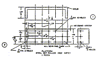
| 1 | Platform, for mounting Radio Receiver BC-342-( ). | |
| 2 | Plate, reinforcing for mounting Antenna Tuning Unit BC-939-( ). | |
| 8 | Plate, strap, for stowage chest. | |
| 2 | 3H4575 | Power Unit PE-75-( ), 1 in use for vehicle and 1 auxiliary for trailer. |
| 1 | Receptacle, with 3 1/4" cover, for outlet box. | |
| 1 | Relay control box, includes hardware. | |
| 1 | 2Z7621.2 | Relay. |
| 2 | 2Z8056 | Roll BG-( ). |
| 6 | Snap, 1 1/2". | |
| 2 | Strap. | |
| 2 | Strap and buckle, No. 14A053-A Hallicrafters Co. | |
| 3 | Strap and tip. | |
| 1 | Strap and buckle, No. 14A076-X Hallicrafters Co. | |
| 1 | Top, canvas, for vehicle. | |
| 5 | Turnbuckle assembly, 7 1/2" length closed, eye and eye type, rods 3/8-16. | |
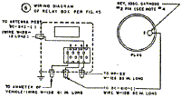
| 15 feet | 1B128 | Wire W-128, for interconnection of relay box. |
21 Modification of Components
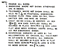
a.) Chest CH-88-A.
Cut Chest CH-88-A in two sections and make the sections into two separate chests for
storage of spare parts by adding plywood end pieces and hardware. Install larger chest in
3/4-ton trailer and smaller chest in Truck, 1/4-ton, 4 x 4. Installation Kit MC-549
contains plywood ends, metal corners, and hardware for modification. Perform the
modification as follows:
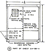
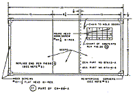
(1) Refer to figure 39. Remove sliding doors on front of Chest CH-88-A. Remove shelves from compartments on left half of chest and two vertical partitions (second and third from left end of chest). Cut left section of chest to 14 5/16-inch length as shown in detail 10. Cut right section 'of chest to 35-inch length as shown in detail 11.
(2) Replace vertical partition at ends with two pieces of plywood supplied with installation kit. Secure with wood screws provided. Place provided metal corners on chest sections as shown in details 10 and 11, figure 39. Remove handle from end of small section, and place on end of large section.
(3) Cut two 7-inch lengths from one door of Chest CH-88-A and use sections to make sliding doors for small chest. Cut sections of doors remainig to make doors for larger chest, as shown in detail 11, figure 39. Replace shelves in chests.
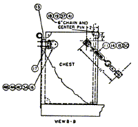
(4) Place proper charts of contents on chest doors. Install doors on chests, and place small chains as shown in details of figure 39.
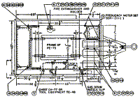
(5) When this installation is made without Installation Kit MC-549, make length of chest sections 14 5/16 inches and 35 inches. Cut two pieces of plywood as shown in detail 12, figure 38. Place ends in chest sections as above, and use partitions provided to support shelves. Remove necessary metal corners, turnbuckle assemblies, escutcheon eyes, snap hooks, and chains from other- chests provided with Radio Set SCR-499-( ) that are not used in the installation, and install on two halves of Chest CH-88-A as shown in figure 39.
b.) Power Unit PE-75-( ).
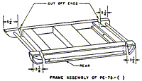
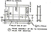
Refer to detail 7, figure 39. Cut ends of frame assembly as shown, in order to mount power
unit on bumper of truck. Perform this modification on both power units so that they may be
interchanged.
c.) Radio Transmitter BC-610-( ).
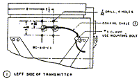
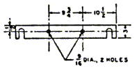
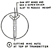
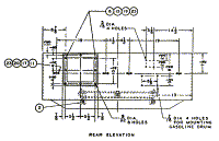
(1) Drill holes in cabinet of transmitter as shown in details 1 and 2,
figure 39. Cut winghead bolts as show, in detail 4, figure 39.
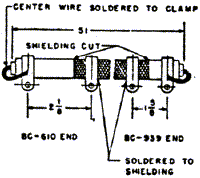
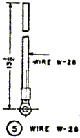
(2) Prepare a coaxial antenna lead as shown in detail 3, figure 39. Prepare a wire antenna lead as shown in detail 5, figure 39, using Wire W-28.
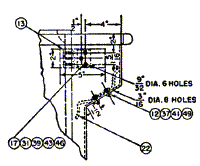
(3) If an early type Radio Transmitter BC-610-( ) is received with sides of cabinet, not reinforced with steel straps, refer to figures 41 and 42 and apply reinforcing straps as directed on drawings.
d.) Radio Receiver BC-342-( ).
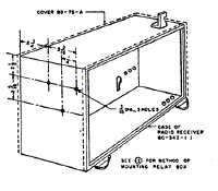
Refer to detail 8, figure 39 and drill cabinet of receiver as indicated. Secure keying
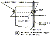
relay box to receiver cabinet as shown in detail 12, figure 39.
e.) Truck 1/4-Ton, 4 x 4.
(1) Remove following items from truck, to reduce weight:
rear bumperettes, horn, spare wheel and tire, rear seat and scat frame, rear view mirror,
lifting handles, and windshield.
(2) Remove holder for 5-gallon gasoline drum, located on left rear of vehicle, and attach holder to right rear of vehicle.
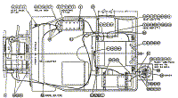
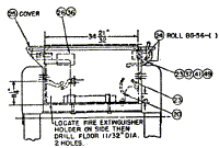
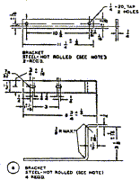
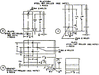
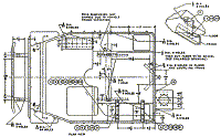
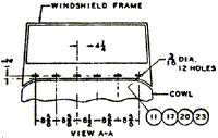
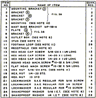
(3) As shown in figure 40, cut two slots through floor of vehicle for brackets, item 2 (detail 5, figure 38). Install brackets in position shown with hard ware provided. These brackets will support front of shock mount on Radio Transmitter BC-610-( ).
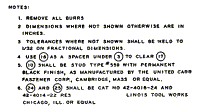
(4) Perform all necessary drilling as shown in figure 40.
f.) Trailer, Bantam, 1/4-Ton
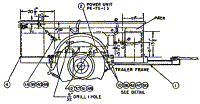
(1) Perform all drilling as indicated in figure 37.
(2) Secure straps in place with hardware provided as shown in figure 37.
(3) When this installation is made without Installation Kit MC-549, necessary straps may be obtained from other chests supplied with Radio Set SCR-499-( ).
Back to Installation of Radio Equipment in Truck, 1/4-Ton, 4 x
4 Index Page.
Army Radio Sales Co. Home Page.
