14. Required Parts
Items necessary for the installation of Radio Set SCR-508-( ), SCR-528-( ), SCR-608-( ),
SCR-628-( ), SCR-808-( ), SCR-828-( ) in Truck 1/4-ton, 4 x 4, are listed below:
| Quantity | Stock No. | Item | ||
| A | B | C | ||
| 1 | 0 | 0 | 2A262 | Antenna A-62, phantom. |
| 0 | 1 | 1 | 2A283 | Antenna A-83, phantom. |
| 1 | 1 | 1 | 2Z1203-422 | Bracket FT-422. |
| 0 | 1 | 0 | 2Z1140 | Box BX-40-( ), for crystals. |
| 1 | 1 | 1 | 2Z1574 | Cabinet CH-74-( ). |
| 0 | 1 | 1 | 6F796 | Chest CH-96, for headsets, spare parts, etc. |
| 1 | 1 | 1 | 2Z2651-423 | Clamp MC-423, for securing Mast Sections MS-51 and MS-52. |
| 1 | 1 | 1 | 2Z2651-424 | Clamp MC-424, for securing Mast Sections MS-52 and MS-53. |
| 1 | 1 | 1 | 6Z3147 | Connector No. 61007 and Bondnut BL-50 (Appleton). |
| 2 | 2 | 2 | 3E1307A-5.5 | Cord CD-307-A, 65", for Headset HS-30-( ). |
| 1 | 1 | 1 | 3E1318 | Cord CD-318( ), for Microphone T-45. |
| 2 | 2 | 2 | 3E1604 | Cord CD-604, 6", for connecting Headset HS-30-( ) to Cord CD-107-A. |
| 1 | 1 | 1 | 2Z3396 | Cover BG-96-( ), for radio set. |
| 0 | 0 | 1 | 2Z3398 | Cover BG-98-( ), for radio set. |
| 1 | 1 | 1 | 2Z3400-108 | Cover BG-108, for mast base. |
| 2 | 2 | 0 | 3H1634 | Dynamotor DM-34-( ), 12-volt, including attached spare parts. ( Only one required for Radio Set SCR-528( ) or SCR-628-( )). |
| 1 | 1 | 0 | 3H1635 | Dynamotor DM-35-( ), 12-volt, including attached spare parts. |
| 0 | 0 | 2 | 3H1664 | Dynamotor DM-64-( ), 12-volt, including attached spare parts. (Only one required for SCR-828-( )). |
| 0 | 0 | 1 | 3H1665 | Dynamotor DM-65-( ), 12-volt, including attached spare parts. |
| 1 | 1 | 1 | 6L50-508V26 | Hardware bag. |
| 2 | 2 | 2 | 2B830 | Headset HS-30-( ). |
| 3 | 3 | 3 | 3G621 | Insulator IN-121. |
| 1 | 1 | 1 | 2A2088-48 | Mast Base MP-48 or MP-48-A including 6 ft of Wire W-128. |
| 1 | 1 | 1 | 2A2090-50 | Mast Bracket MP-50. |
| 1 | 1 | 1 | 2A2351 | Mast Section MS-51. |
| 1 | 1 | 1 | 2A2352 | Mast Section MS-52. |
| 1 | 1 | 1 | 2A2353 | Mast Section MS-53. |
| 1 | 1 | 1 | 2B1617 | Microphone T-17-( ). |
| 1 | 1 | 1 | 2B1545 | Microphone T-45. |
| 2 | 2 | 2 | 2B1567 | Microphone Cover M-367. |
| 1 | 1 | 1 | 2Z6721-237 | Mounting FT-237-( ), including Cord CO-278 and necessary hardware for mounting. |
| 1 | 1 | 1 | 2Z7721-285 | Mounting FT-285-( ), including hardware for mounting. |
| 2 | 0 | 0 | 2C4403 | RadioReceiver BC-603-( ) includes set of installed tubes and spare fuses and lamps (one only required for SCR-528-( )). |
| 1 | 0 | 0 | 2C6494 | Radio Transmitter BC-604-( ), includes installed tubes and necessary crystals. |
| 0 | 2 | 0 | 2C4460-683 | Radio Receiver BC-683-( ), including tubes, fuses, and lamps (one only required for SCR-628-( )). |
| 0 | 1 | 0 | 2C6530-684 | Radio Transmitter BC-684-( ), including tubes and necessary crystals. |
| 0 | 0 | 2 | 2C4923 | Radio Receiver BC-923-( ), including tubes, fuses, and lamps (one only required for SCR-828-( )). |
| 0 | 0 | 1 | 2C6596-924 | Radio Transmitter BC-924-( ), including tubes and necessory crystals. |
| 2 | 2 | 2 | 2Z7069-429 | Reinforcing Plate FT-429. |
| 1 | 1 | 1 | 2Z8056 | Roll BG-56-( ), for antenna mast sections. |
| 2 | 0 | 2 | Strap ( item 45, figure 25 ). | |
| ( Quantity A ) SCR-508-( ), SCR-528-( ) ( Quantity B ) SCR-608-( ), SCR-628-( ) ( Quantity C ) SCR-808-( ), SCR-828-( ) |
||||
|
||||||||||||


15. Assembly and Installation
a.) Preliminary Check.
Radio Set SCR-508-( ), SCR-528-( ), SCR-608-( ), SCR-628-( ), SCR-808-( ), or SCR828-( )
may be installed in truck, 1/4-ton, 4 x 4, with either of the following 12-volt conversion
kits. Check to see that the conversion has been made before beginning installation.
(1) Under-the-hood conversion kit in which all 6-volt electrical components of the vehicle are replaced by 12-volt components. Two 6-volt storage batteries, one originally furnished with the truck, and one supplied with the conversion kit, are installed between the front seats to furnish, in series, 12-volt power supply for both the radio set and the vehicular system.
(2) Power-take-off conversion kit in which a 12-volt generator and regulator is mounted over the transmission of the vehicle, to be driven by a belt and pulley operated off the shaft of the transmission. Two 6-volt storage batteries are supplied with the conversion kit and are installed, one behind each front seat. These two batteries, in series, furnish 12-volt power for operation of the set independently of the 6-volt system of the vehicle.
b.) Procedure.
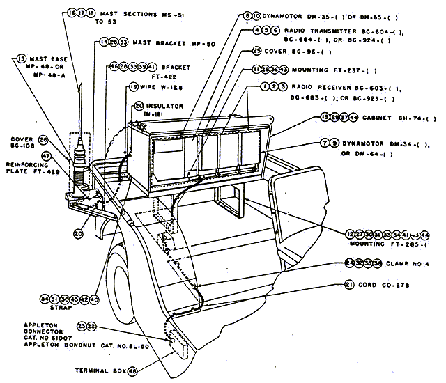
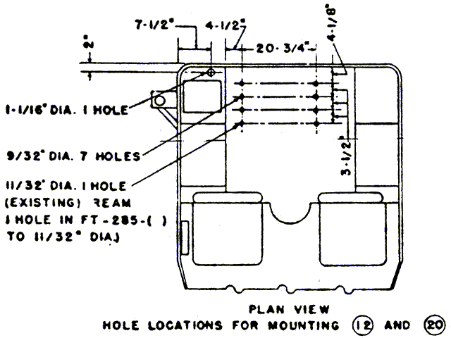
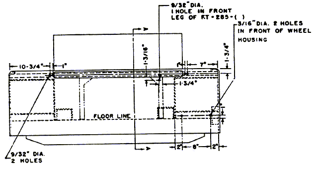
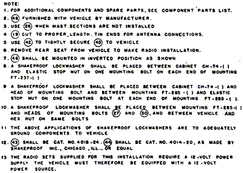
Components of the radio set should be installed as shown in figure 25 and as directed
below.
Part and Location |
Method and Materials |
| Mounting FT-285-( ), and Strap (item 45, figure 25), in rear of vehicle, center. | Attach the mounting to the floor of the vehicle with the hardware provided. Secure top of mounting to vehicle with strap (one at each end) as shown in figure 25. |
| Cabinet CH-74-( ), on Mounting FT-285( ). | Attach to the mounting with the screws and stop-nuts supplied in the bottom of the cabinet. |
| Mounting FT-237-( ), in Cabinet CH-74-( ). | Attach the mounting to the floor of the cabinet with the hardware supplied with the mounting. Route Power Cord CO-278 to the car terminal box and secure as shown in figure 25. |
| Mast Bracket MP-50, Bracket FT-422, and Reinforcing Plate FT-429, on the right side of the vehicle body, at the rear. | Attach the mast bracket to the wheel housing with the reinforcing plate on the inside as shown in figure 25, using the hardware provided. |
| Insulators IN-121. | Install one insulator through the hole in the mast bracket and vehicle. Install the other insulators through the hole in the top of the right rear wheelwell and through one end of Cabinet CH-74-( ), as shown in figure 25. |
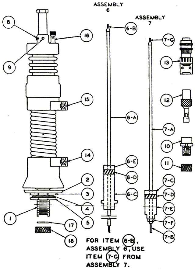
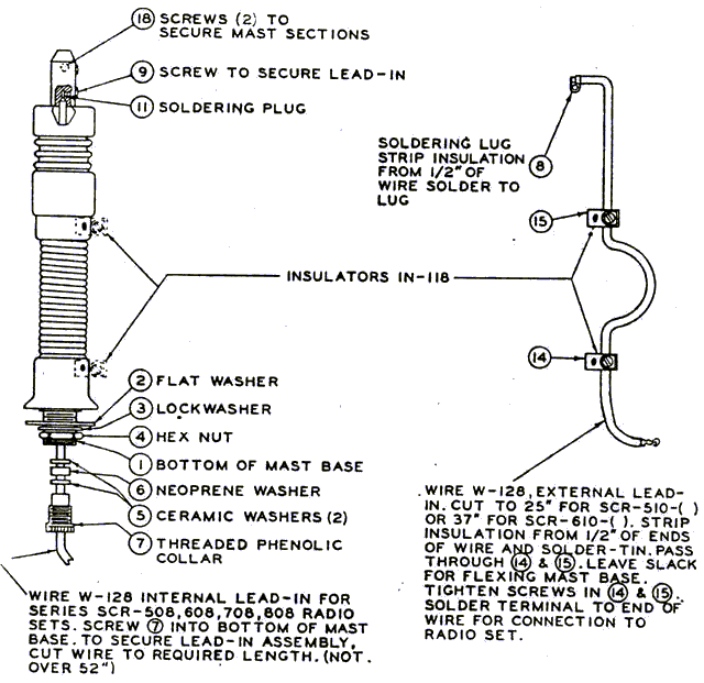
| Mast Base MP-48 or MP-48-A, on Mast Bracket MP-50. | If Mast Base MP-48 is supplied, refer to figure 26 and assemble as
follows: Remove nuts and washers (items 2, 3, 4, and 5) from stem (item 1). Loosen setscrews (items 8 and 9) and pull assembly 7 out of the mast base and stow the assembly. Prepare assembly 6 as follows: Strip 1/2-inch of the insulation from each end of the proper length of wire W-128; clean and tin the ends. Solder lug (item 6B) to one end. Place the porcelain insulator (item 6C), neoprene washer. (item 6D), and ceramic insulator (item 6E) over Wire W-128. Insert the assembly into the mast base and secure with setscrews (items 8 and 9). Make certain that item 6B is inserted into the mast base as far as it will go. Insert Wire W-128 and the stem (item 1) through the hole in the mast bracket and secure in place with items 2, 3, 4, and 5. Flex the mast base 90' and screw the retaining collar (item 18) on the end of the mast base stem (item 1) to secure the assembly in the mast base. Route the lead-in wire through Insulators IN-21 and attach to the TR binding post on Mounting FT-237-( ). If Mast Base MP-49-A is supplied, assemble as shown in figure 27. |
| Mast Sections MS-51 to MS-53 and Clamps MC-423 and MC-424, on the mast base. | Screw the mast sections together and secure with the clamps. Fasten the clamps to the male end of the mast sections. Then screw the mast antenna into the mast base. When not in use, carry the mast sections in Roll BG-56-( ). |
| Cover BG-108. | Place on the mast base when the mast sections are not in use. |
| Radio Receiver BC-603-( ) or BC-683-( ) and Dynamotor DM-34-( ), on
Mounting FT-237-( ). (Only one receiver and one dynamotor are used with Radio Set SCR-528-( ) or SCR-628- ( )). |
If Dynamotor DM-34-( ) is not already installed, proceed as follows: Remove receiver chassis from cabinet by loosening the screw lock in the rear center of the cabinet. Install the dynamotor unit on the top rear of the receiver chassis by means of four screws through its base. Place the receiver on Mounting FT-237-( ) in the position shown in figure 25 and secure by means of the thumbscrew lock. |
| Radio Transmitter BC-604-( ) or BC-684-( ) and Dynamotor DM-35-( ) on Mounting FT-237-( ). | If Dynamotor DM-35-( ) is not already installed in Radio Transmitter
BC-604-( ) or BC-684( ), proceed as follows: Remove crystal case from the transmitter cabinet by loosening the two screw locks on the front panel and pulling out the crystal case. Loosen the four screw locks holding cover on top of transmitter and remove the cover. Install the dynamotor unit in the left rear of the transmitter chassis by means of four screws through its base. Place transmitter unit on Mounting FT-237-( ) in the position shown in f igure 25 and secure by means of the thumbscrew lock. |
| Radio Receiver BC-923-( ) and Dynamotor DM-64-( ), on Mounting FT-237-( ). (Only one receiver and dynamotor are used with Radio Set SCR-828-( )). | If Dynamotor M-64-( ) is not already installed in Radio Receiver
BC-923-( ), proceed as follows: Remove the, shield cover of the receiver by loosening the fastener at the back of the cover and sliding the cover from the chassis. Mount the dynamotor on the rear of the chassis and secure with the hold-on screws. Make certain that the female plug on the dynamotor engages properly with the male plug on the chassis. Replace the dust cover in its original position, and tighten the fastener. Place the receiver on the mounting as shown in figure 25 and secure with the thumbscrew locks. |
| Radio Transmitter BC-924-( ) and Dynamotor DM-65-( ), on Mounting FT-237-A (For Radio Set SCR-808-( ) or SCR-828-( )). | If Dynamotor DM-65-( ) is not already installed in Radio Transmitter
BC-924-( ), proceed as follows: Remove the dust cover of the transmitter by loosening two fasteners on the back of the cover and lifting the cover off. Place the dynamotor in position on the transmitter and secure with the slide fasteners. Replace the cover on the transmitter and tighten the fasteners. Place the transmitter on the mounting as shown in figure 25 and secure with the thumbscrew latch. |
| Antenna A-62, phantom. | For installation with Radio Set SCR-508-( ) or SCR-528-( ), see TB11-600-1. |
c.) Cording and Wiring.
(1) Cord and wire Radio Set SCR-508-( ), SCR-528-( ), SCR608-( ),
SCR-628-( ), SCR-808-( ), or SCR-828-( ) as shown in figure 25. Connect and secure so as
not to interfere with the accessibility and operation of the equipment. Enough slack must
he left to permit free movement of all units having shock mounting. Cording or cable
likely to rub against sharp edges should he taped with at least two layers to prevent
damage. Solder-tin all wire ends.
(2) To prevent accidental shorts of the battery, do not connect the positive 12-volt and negative 12-volt leads (in the terminal box) until all other connections have been completed.
|
|
Back to Installation of Radio Equipment in Truck, 1/4-Ton, 4 x 4 Index Page.
Army Radio Sales Co. Home Page.