16 Required Parts
Items necessary for the installation of Radio Set SCR-510-( ) or SCR-610-( ) in Truck, 1/4-ton, 4 x 4, are listed below:
Quantity |
Stock No. | Item | |
| SCR-510 | SCR-610 | ||
| 1 | 1 | 6Q349 | Alignment Tool TL-207. |
| **a 1 | **a 1 | 3A41 | Battery BA-41, for Radio Receiver and Transmitter BC-620-( ) or BC-659-( ), internal. |
| 0 | 1 | 2Z1140 | Box BX-40-( ), for crystals. |
| 1 | 1 | 2Z6721-419 | Bracket FT-419, for Mounting FT-250-( ). |
| 1 | 1 | 2ZI203-420 | Bracket FT-420, for Mounting FT-250-( ). |
| 1 | 1 | 2Z1203-422 | Bracket FT-422 (brush guard for Mast Bracket MP-50). |
| 0 | 1 | 2Z2651-423 | Clamp MC-423, for securing Mast Sections MS-51 and MS-52. |
| 1 | 1 | 2Z2651-424 | Clamp MC-424, for securing Mast Sections MS-52 and MS-53. |
| 1 | 1 | 6Z3147 | Connector No. 61007 and Bondnut BL-50 (Appleton). |
| **b 2 | **b 2 | 3E1307A-5.5 | Cord CD-307-A, 65", for Headset HS-30-( ). |
| **b 2 | **b 2 | 3E1605 | Cord CD-605 for Headset HS-30-( ). |
| **b 2 | **b 2 | 3E1604 | Cord CD-604 for connecting Cord CD-307-A to Headset HS-30-( ). |
| 1 | 1 | 2Z3400-153 | Cover BG-153, for radio set. |
| 1 | 1 | 2Z3400-108 | Cover BG-108, for mast base. |
| 2 | 2 | 2B830 | Headset HS-30-( ). |
| 1 | 1 | 6L50-51OV26 | Hardware bag. |
| **c 1 | **c 1 | 2A2088-48 | Mast Base MP-48-A or MP-48. |
| 1 | 1 | 2A2090-50 | Mast Bracket MP-50. |
| 0 | 1 | 2A2351 | Mast Section MS-51. |
| 1 | 1 | 2A2352 | Mast Section MS-52. |
| 1 | 1 | 2A2353 | Mast Section MS-53. |
| 1 | 1 | 2B1617 | Microphone T-17-( ). |
| 1 | 1 | 2B1645 | Microphone T-45. |
| 1 | 1 | 2Z6721-250 | Mounting FT-250-( ). |
| **d 1 | **d 1 | 3H4496-120 | Power Unit PE-120-( ), (includes 2 Vibrator VB-12 and spare capacitors. |
| 1 | 0 | 2C5360 | Radio Receiver and Transmitter BC-620-( ), includes 2 crystals in Holders FT-243 and set of tubes installed. |
| 0 | 1 | 2C5379 | Radio Receiver and Transmitter BC-659-( ), includes 2 crystals in Holders FT-243 and set of tubes installed. |
| 2 | 2 | 2Z7069-429 | Reinforcing Plate FT-429-( ), for Mast Bracket MP-50. |
| 1 | 1 | 2Z8056 | Roll BG-56-( ), for antenna mast sections. |
| 2 | 2 | 3H6712 | Vibrator VB-12, 6-volt. |
| 11ft | 11ft | 1B128 | Wire W-128. |
| **a) To be requisitioned from the nearest Signal Corps Depot or Signal Section of an Army Service Forces Depot. | |||
| **b) Cord CD-307-A and CD-604 may be substituted for Cord CD-605. | |||
| **c) When Mast Base MP-48 is supplied, 7 feet of Wire W-128 must be used. | |||
| **d) Plate Supply Unit PE-97-( ) and PE-117-( ) may be substituted for Power unit PE-120-( ) in Radio Sets SCR-510-( ) and SCR-610-( ), respectively. When those subsituitions are made, Vibrator VB-12 is not required. | |||
17 Assembly and Installation
a.) Preliminary Check.
Truck, 1/4-ton, 4 x 4, ordinarily has a 6-volt electrical system. These instructions cover
Radio Set SCR-510-( ) or SCR-610-( ) for 6-volt operation. Conversion of the electrical
system is made in some vehicles to permit installation of radio equipment requiring 12
volts for operation. These conversions may be either a 12-volt under-hood conversion or a
power take-off conversion. Radio Set SCR-510-( ) or SCR-610-( ) as covered in these
instructions, cannot be used with the power take-off conversion, due to interference with
the battery boxes supplied with the power take-off conversion. Before beginning the
installation, make sure that the power units are adjusted for the same voltage as that
supplied by the vehicle in which the radio set is to be installed, and that vibrators for
the correct voltage are supplied.
b.) Procedure.
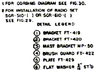
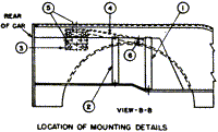
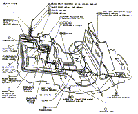
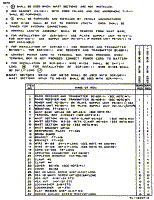
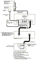
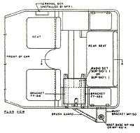
Components of the radio set should be installed as shown in figures 28, 29, and 30, and as
directed below:
c.) Cording and Wiring
(1) Cord and wire Radio Set SCR-510-( ) or SCR-610-( ) as shown in
figures 29 and 30. Connect and secure so as not to interfere with the accessibility and
operation of the equipment. Enough slack must be left to permit free movement of all units
having shock mounting. Cording and cable likely to rub against sharp edges should he taped
with at least two layers to prevent damage. Solder-tin all wire ends.
(2) To prevent accidental shorts of the battery, do not connect the positive 6-volt and negative 6-volt leads (on the vehicle battery or in the terminal box, if supplied) until all other connections have been completed.
Part and Location |
Method and Materials |
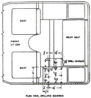
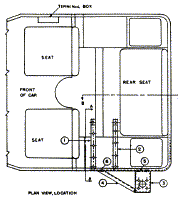
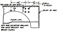
| Brackets (FT-419 and 420) for Mounting FT-250-( ) over left rear wheel housing. | Refer to plan view, drilling diagram, figure 28, for details and mounting holes, and install brackets as shown in figure 29. |
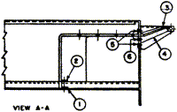
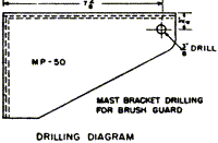
| Mast Bracket MP-50, and Reinforcing Plate FT-429-( ) on left wall of vehicle as shown in figure 29. | Drill holes as shown in the drilling diagram in figure 28 and mount the brackets in place with the hardware provided. |
| Bracket FT-422 (brush guard), on the left wall of the vehicle as shown in figure 29. | Mount in place with the hardware provided. |
| Mast Base MP-48 or MP-48-A and Wire W-128 on Mast Bracket MP-50, as shown in figures 29 and 30. | If Mast Base MP-48 in supplied, refer to figure 26 and proceed as
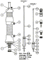
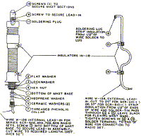
follows: Remove items 2, 3, 4, 5, 17, and 18 from item 1. If the internal lead-in, assembly 7, is installed in the mast base, remove the assembly and stow it. Cut Wire W-128 to 24" for Radio Set SCR-510-( ) or 36" for Radio Set SCR-610-( ). Strip insulation from the ends of the wire, solder-tin and pass one end of the wire through insulators, items 14 and 15, and secure to binding post, item 16. Leave enough slack for flexing the mast base. Tighten the screws in items 14 and 15. Insert item 1 through the hole in the mast bracket. Replace items 2, 3, 4, and 5 on item 1 and tighten securely. Replace items 17 and 18 on item 1, to prevent dirt and moisture from collecting inside the mast base. If Mast Base MP-48-A is supplied, prepare Wire W-128 as directed above. Refer to figure 27 and pass the wire through the insulators, items 14 and 15. Leave enough slack for flexing the mast base. Tighten the screws in items 14 and 15. Solder terminal, item 8, to the wire and connect to she terminal on the mast base with item 9. Solder another terminal to the other end of Wire W-128 for connection to the radio set. Remove items 2, 3, and 4 from the mast base stem. Mount the mast base on the mast bracket and secure with items 2, 3, and 4. |
| Mounting FT-250-( ) on brackets, over the left rear wheel housing, as shown in figure 29. | Place the mounting on the brackets and secure with the hardware provided. |
| Power Unit PE-120-( ) and Vibrator VB-12 on Mounting FT-250-( ). | Raise the lid of Power Unit PE-120-( ) and remove the cover of the power pack. Refer to the diagram on the cover and be sure that the change over plug is in the 6-volt position (arrow pointing to six). Set the connector link in the BC-620 position for Radio Set SCR-510-( ) or in the BC-659 position for Radio Set SCR-610-( ). Plug Vibrator VB-12 into its socket and replace the cover of the power pack. Close the lid of the power unit and place the unit on the mounting. Secure with the book fasteners provided. |
| Radio Receiver and Transmitter BC-620( ) or BC-659-( ) and Battery BA-41, on Power Unit PE-120-( ). | If Battery BA-41 is not already installed in the receiver and
transmitter, proceed as follows: Remove the screws around the outer edge of the front Panel and Pull the receiver and transmitter chassis Out of its case. Remove the cover of the battery cornpartrnent located on the chassis near the front panel. Place Battery BA-41 into the compartment, being careful to engage the plug into the socket of the battery. Replace the cover. Before replacing the chassis in its case, make sure that all tubes are firmly pressed down into their proper sockets, that the crystals for the desired operating frequencies are in their proper sockets with the retaining clip in position, and that the two toggle - switches near the left side of the chassis are in the ON Position. Mount the receiver and transmitter on the power unit and secure with the Provided catch clips. |
| Mast Sections MS-52 and MS-53 and Clamp MC-424. (Add Mast Section MS-51 and Clamp MC-423 for Radio Set SCR-610-( ). | Screw the mast sections together and secure with the clamps. Fasten the clamps to the male end of the mast sections. Then screw the mast antenna into the mast base. When not in use, carry the mast sections in Roll BG-56-( ). |
| Cover BG-108. | Place over the mast base when the mast sections are not in use. |
| Power Cord, Connector No. 61007, Bondnut BL-50, and Clamps No. 4 and No. 5. | Route power cord to the vehicle battery as shown in figure 29. Use the connector and bondnut to protect the cord as it passes through the hole in the vehicle floor board. If the vehicle is equipped with a terminal box, use the connector and bondnut to bush and secure the cord as it passes through the knockout hole in the terminal box. |
Back to Installation of Radio Equipment in Truck, 1/4-Ton, 4 x 4 Index Page.
Army Radio Sales Co. Home Page.
