23 Required Parts
Items necessary for the installation of Radio Set SCR-694-C in Truck, 1/4-ton, 4x4, are
listed below:
Quantity |
Stock No. | Item |
| 2Z551-172 | Bag BG-172, for accessorys equipment. | |
| 2Z551-173 | Bag BG-173, for Radio Receiver and Transmitter BC1306. | |
| 3H160-175 | Bag BG-175, for Generator GN-58 (used in portable operation). | |
| 6F153 | Box BX-53, for spare tubes, lamps, and brushes. | |
| 6Z3147 | Connector No. 61007 and Bondnut BL-50. | |
| 3E1307-5.5 | Cord CD-307-A. | |
| 3E1318 | Cord CD-318-A. | |
| 3E1604 | Cord CD-604. | |
| 3E1999-86 | Cord CD-1086. | |
| 6Z6958 | Footman's loop. | |
| 2Z4600-85 | Frame FM-85. | |
| 6L50-694V26 | Hardware bag. | |
| 2B830 | Headset HS-30. | |
| 3G604 | Insulator IN-104, including spare. | |
| 3Z3445 | Key-J45. | |
| 2A2088-65 | Mast Base MP-65. | |
| 2A2090-50 | Mast Base Bracket MP-50. | |
| 2A2416 | Mast Section MS-116, including three spares. | |
| 2A2417 | Mast Section MS-117, including spare. | |
| 2A2418 | Mast Section MS-118, including spare. | |
| 2B1617 | Microphone T-17, a spare. | |
| 2B1645 | Microphone T-45. | |
| 2B1567 | Microphone Cover M-367. | |
| 2Z6727-482 | Mounting FT-482, including hardware. | |
| 3F3986-34 | Phantom Antenna A-34. | |
| 2C5395-1306 | Radio Receiver and Transmitter BC-1306, including Panel Cover M-404. | |
| 2Z6721-429 | Reinforcing Plate FT-429. | |
| 2Z8060-174 | Roll BG-174. | |
| 2Z9050-51 | Strap ST-51, for Bag BG-175. | |
| 2Z9050-52 | Strap ST-62, for Bag BG-175. | |
| Support for Vibrator Power Unit PE-237. | ||
| 6D13087C | TM 11-230C for Radio Set SCR-694-C. | |
| 3H6800-237 | Vibrator Power Unit PE-237, including hardware. | |
| 1B128 | Wire W128. | |
| *While Generator GN-58 is used only in portable operation, It's bag, Bag BG-175, is Installed in the vehicle. | ||
24 Assembly and Installation
a.) Preliminary Modification of Truck, 1/4-Ton, 4 x 4.
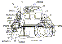
See figure 47, and perform the following operations:
(1) Drill holes through cowl, right and left wheelwell, body reinforcing
bead, and floor of vehicle, as shown in Mounting Hole Locations.
(2) Drill hole through right side of vehicle, rear, as shown in View A-A.
(3) Drill holes through left side of vehicle, as shown in View B-B.
(4) Drill holes through side panel of left rear stowage compartment, as
shown in View C-C.
(5) Drill holes through rear of vehicle, left, as shown in View D-D.
b.) Procedure
Components of the radio set should he installed as shown in figure 47 and as directed
below:
Part and Location |
Method and Materials |
| Wire W-128 and terminal (items 13, 14, and 49, figure 47). | Cut a 14-inch length of Wire W-128 for ground connection. Strip about 1/2 inch of insulation from each end. Solder-tin tips, and solder a terminal, supplied with hardware bag, to one end of the wire. Cut a 5-foot length Wire W-128 for antenna connection. Strip about 1/2 inch insulation from each end, and solder-tin tips. |
| Frame FM-85 and Reinforcing Plates FT-429 (items 4 and 7, figure 47), on left rear wheelwell. | Locate Frame FM-85 in position, as shown in figure 47, Pictorial View. With hardware Provided, secure bottom of Frame FM-429 on under side. Secure back of Frame FM-85 to left side of vehicle with hardware provided. Secure the terminal soldered to the 14-inch length of Wire W-128, to the rear ward screw as shown in figure 47, Detail A. |
| Mounting FT-482 (items 3, figure 47), on Frame FM-85. | Secure in position with hardware provided, as shown figure 47. |
| Radio Receiver and Transmitter BC-1306 and Panel Cover M-404 (items 1 and 26, figure 47), on Mounting FT-482. | Place Panel Cover M-404 over back of Radio Receiver and Transmitter BC-1306. Place radio receiver and transmitter on mounting FT-482, and secure with straps provided. Secure panel cover to mounting with straps provided. When vehicle is to be transported or stored, remove receiver and transmitter and panel cover from the mounting. Place panel cover over front panel of receiver and transniitter, securing with spring catch clips provided. Then replace unit on Mounting FT-482. |
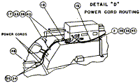
| Vibrator Power Unit PE-237, support, and connector No. 61007 and Bondnut BL-50 (items 2, 6, 24, and 25, figure 47), over right wheelwell. | See figure 47. Pictorial View. Secure shock mount feet of vibrator power
unit on support with hardware provided. Screws must be inserted from underneath support.
Place power unit over right wheelwell, and secure forward end to wheelwell with hardware
provided. Secure support to floor and to right side of vehicle as shown in figure 47.
Adjust the power unit for 6-volt operation by removing the cover and setting the voltage
adjusting switch to 6-VOLT POSITION. Disconnect power cords from terminal strip on chassis
of vibrator power unit by loosening terminals on terminal strip, disassembling bushing
connectors, and pulling out power cords. Disassemble supplied connectors No.61007 and
Bondnuts BL-50. Pass each power cord through shell, rubber insert, and end cap of
connectors No. 61007. Replace and connect power cords in original location, tighten
bushing connectors, and replace cover of vibrator power unit. Route and secure power cords
as shown in figure 47, Detail D. Pass power cords into terminal box through knock-out
holes, and secure with connectors and bondnuts previously placed on cords. Connect power
cord terminals to positive and negative terminals in terminal box observing proper
polarity. Warning: If vehicle is equipped with 12-volt conversion adjust Vibrator. Power Unit PF-237 for 12-volt operation. |
| Mast Base Bracket MP-50 (item 8, figure 47), on left rear of vehicle. | See figure 47, Detail C, and drill holes in mast base bracket as shown. Secure mast base bracket on left rear of vehicle with hardware provided, as shown in figure 47. |
| Insulators IN-104 (item 27, figure 47). | Install three Insulators IN-104 on body reinforcing bead of vehicle, left side, and one insulator on left side of Mast Base Bracket MP-50 as shown in figure 47. |
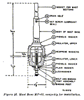
| Mast Base MP-65 (item 9, figure 47), on Mast Base Bracket MP-50. | Install Mast Base MP-65 on mast base bracket as follows: See figure 48. Disassemble Mast Base MP-50 by holding body of mast base and turning bolt and binding post assembly, item 10, in a counterclockwise direction. Place upper insulator, item 4, over hole in mast base bracket. Place phenolic washer, item 3, over item 4 and insert body of mast base, item 2, through hole in items 3 and 4 and mast base bracket. Insert bolt and binding post, item 10, through holes in items 9, 8, 7, and 6, respectively. Insert item 10 into item 2, from underneath mast base bracket. Turn item 2 clockwise, while holding item 10 with a 9/16-inch open-end wrench, until mast base is tightened securely. Connect one end of prepared 5-foot length of Wire W-128 to binding post on bottom of mast base. Route wire through Insulators IN-104 and connect, other end to antenna binding post on Radio Receiver and Transmitter BC-1306. Wrap friction tape around Wire W-128 at first and fourth Insulator IN-104 to keep wire taut between insulators. |
| Mast Sections MS-116, MS-117, and MS-118 (items 10, 11, and 12, figure 47), on Mast Base MP-65. | Screw mast sections together, and screw assembled antenna into mast base. Place spare mast sections in Roll BG-174. When mast sections are not in use stow in Roll BG-174. |
| Clips (items 16, figure 47). | With hardware provided, secure three clips on body, reinforcing bead, at rear, as shown in figure 47. |
| Cord CD-1086 (item 15, figure 47). | Connect one end of Cord CD-1086 (7-foot length) to provided socket on front panel of Radio Receiver and Transmitter BC-1306. Connect other end to Vibrator Power Unit PE-237, making sure that retainer rings over plugs are drawn up tight. Secure Cord CD-1086 in place along rear bead of vehicle with clips previously installed. |
| Hook (item 50, figure 47). | Secure hook, provided in hardware bag, as shown in figure 47, with hardware provided. |
| Footman's loop and Straps ST-51 and ST-52 (items 23, 21, and 22, figure 47). | See figure 47. Pictorial View. Install three footman's loops on cowl of vehicle for securing Roll BG-174. Insert a footmans loop through loop of Strap ST-51 and Secure footman's loop on body reinforcing bead, left side rear. Insert a footman's loop through loop of Strap ST-52 and secure footman's loop on side panel of compartment in left rear of vehicle as shown. All hardware require for securing footman's loops is provided in hardware bag. |
| Roll BG-174 (item 20. figure 47). | Stow equipment in Roll BG-174 as directed in TM 11-230C. Secure roll to footman's loops on cowl of vehicle, as shown in figure 47, Pictorial View. |
| Bag BG-175 (item 19, figure 47). | Stow portable Generator GN-58 in Bag BG-175, and secure over left rear stowage compartment of vehicle with Straps ST-51 and ST-52 as shown. |
| Bag BG-173. | Use on Radio Receiver and Transmitter BC-1306 when removed from vehicle for portable operation. Stow Bag BC-173 in vehicle at discretion of using arm. |
| Bag BG-172. | Stow auxiliary equipment in Bag BG-172 as directed in TM 11-230C. Stow Bag BG-172 in vehicle at discretion of using arm. |
Back to Installation of Radio Equipment in Truck, 1/4-Ton, 4 x
4 Index Page.
Army Radio Sales Co. Home Page.


