|
Radio Set AN/VRC-1-( ) is procured with one high-frequency radio transmitting and
receiving set ( Radio Set SCR-193-( ) ), and one very-high-frequency radio transmitting
and receiving set ( Radio Set SCR-542-( ) ), assembled in Cabinet CH-217, as shown in
figures 31, 33, and 34.
a.) Components.
The following list of component parts of Radio Set AN/VRC-1-( ) is included for reference
purposes:
| Quantity |
Stock No. |
Item |
| b2 |
|
Bonding Jumper, 1/2" wide, 5" long. |
| 2 |
|
Bonding Jumper, 1/2" wide, 8" long. |
| a1 |
|
Bonding Jumper, 1/2" wide, 5" long. |
| a1 |
|
Bonding Jumper, 1/2" wide, 3" long. |
| b2 |
|
Capacitors, 0.01 mf. (for Dynamotor Unit PE-98) |
| 1 |
6F915 |
Cabinet CH-217, including Mast, Rack FT-476, brackets, and hardware for mounting. |
| b2 ft |
1B1543 |
Cable WC-543 or WC-549 (coaxial). |
| a1 |
2ZI848 |
CS-48, for transmitter tuning units. |
| b1 |
2Z1880 |
Case CS-80-( ) M, modified, with six Lord Shock mounts, Type 153-PH-24, replacing
original mounts. |
| a1 |
3E1237 |
Cord CD-237, connects Dynamotor Unit BD-77-( ) to Radio Transmitter BC-191-( ). |
| a1 |
3E1358 |
Cord CD-358, connects Radio Transmitter BC-191-( ) to terminal box. |
| a1 |
3E1411 |
Cord CD-411, connects Radio Receiver BC-312-( ) to terminal box. |
| a1 |
3E1165 |
Cord CD-165-( ), connects Dynamotor Unit BD-77-( ) to terminal box. |
| a1 |
3E1424 |
Cord CD-424. |
| b1 |
3E6000-58 |
Cord CX-58/VRC-1. |
| a2 |
2Z2651-421 |
Clamp MC-421, for securing Mast Sections MS-49 and MS-50, one in use, one spare. |
| a2 |
2Z2651-422 |
Clamp MC-422, for securing Mast Sections MS-50 and MS-51; one in use, one spare. |
| a2 |
2Z2651-423 |
Clamp MC-423, for securing Mast Sections MS-51 and MS-52, one in use, one spare. |
| a2 |
2Z2651-424 |
Clamp MC-424, for securing Mast Sections MS-52 and MS-53, one in use, one spare. |
| b1 |
3E6000-59 |
Cord CX-59/VRC-1. |
| b1 |
3E6000-60 |
Cord CX-60/VRC-1. |
| b1 |
3E6000-61 |
Cord CX-41/MC-1. |
| b1 |
3E6000-63 |
Cord CX-WIVRC-1. |
| 1 |
3E2260 |
Cord CD-260, connects terminal box to vehicle terminal box. |
| b4 |
3E2213 |
Cordage CO-213. |
| a1 |
2Z3375 |
Cover BG-75-( ), for Radio Receiver BC-312-( ). |
| a1 |
2Z3378 |
Cover BG-78-( ), for Radio Transmitter BC-191-( ). |
| a1 |
3H1359 |
Cover BG-79-( ), for Dynamotor Unit BD-77-( ). |
| b1 |
6Z3147 |
Connector No. 61007 and Bondnut No. BL-50 (Appleton). |
| a1 |
3H1777 |
Dynamotor Unit BD-77-( ), including mounds FT-107-( ) and spare fuses and brushes. |
| b1 |
3H1898 |
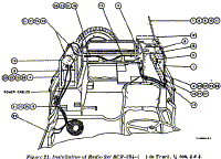
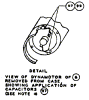
Dynamotor Unit PE-98-( ), modified by insulation of two 0.01mf capacitors, listed
above, as shown in figure 21. |
| b2 |
3ZI959 |
Fuse, FU-59 40 amp, Littefuse type 4AG, one in use, one spare. |
| b1 |
3Z2843 |
Fuse Block, with clips (for 1 1/4" x 1/4" fuse). |
| 1 |
|
Hardware Kit, for Mounting components. |
| a4 |
3G604 |
Insulator IN-104. |
| a3 |
3G621 |
Ingulator IN-121. |
| b1 |
2C1738 |
Interphone Control Box BC-606-( ), Including attached hardware. |
| b1 |
2Z5600-33 |
Juncton Box J-33/VRC-1. |
| b1 |
2B1770-299 |
Microphone Adapter M-299, including plug. |
| a1 |
2Z6712 |
Mounting FT-172, snubber for Radio Transmitter BC-191-( ), including Hardware. |
| a1 |
2Z6718 |
Mounting FT-178, snubber for Radio Receiver BC-312-( ), including hardware. |
| b2 |
2Z6721-475 |
Mounting Bracket FT-475. |
| b1 |
2Z7226-173.2 |
Plug PL-P173. |
| b1 |
2Z7380-244 |
Rack FT-244-( ). |
| a1 |
2C4312 |
Radio Receiver BC-312-( ), including one Mounting FT-162, one Dynamotor DM-21-( ) and
one set of tubes installed, and bag of spare fuses and lamps. |
| b1 |
2C4424 |
Radio Receiver BC-624-( ), including two Crystal Units DC-11-( ) or CR-1-( )/AR, one
set of tubes installed, and one set of tubes in Box BX-19-( ). |
| b1 |
2C6525 |
Radio Transmitter BC-625-( ), includes two Crystal Units DC-11-( ) or CR-1( )/AR and
set of tubes installed. |
| a1 |
2C6191 |
Radio Transmitter BC-191-( ), includes one Mounting FT-151-( ), fuses, lamps, one set
of tubes installed, spare tubes in Box BX-8, one Socket Cap M-164-( ), and two Socket Caps
M-165-( ). |
| b1 |
2C3347 |
Radio Control Box BC-602-( ). |
| b6 |
|
Shockmounts, Lord Mfg. Co. Type 153PH-24, for Case CS-80. |
| a1 |
2Z8793 |
Socket Cap M-163-( ), for Radio Transmitter BC-191-( ). |
| a1 |
2Z9313 |
Terminal Block TM-183, for terminal box. |
| 1 |
2B1172.3 |
Terminal Box. |
| a1 |
2C8006 |
Transmitter Tuning Unit TU-6-( ). |
| a1 |
2C8007 |
Transmitter Tuning Unit TU-7-( ). |
| a15 ft |
1B128 |
Wire W-128. |
a Indicates components of high-frequency portion ( SCR-193-( ) ) of
Radio Set AN/VRC-1-( ).
b Indicates components of very-high-frequency portion ( SCR-542-( ) ) of Radio Set
AN/VRC-1-( ). |
 |
 |
 |
 |
 |
 |
 |
 |
 |
 |
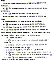 |
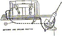
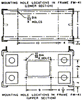
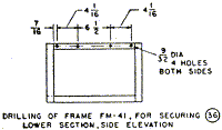
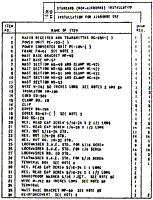
| Figure 21:
Installation of Radio Set SCR-284-( ) in Truck, 1/4 ton 4x4 |
|
 |
 |
 |
 |
 |
 |
 |
 |
 |
 |
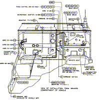
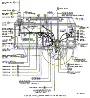
| Figure 31:
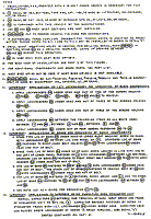
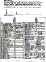
Installation of Radio Set AN/VRC-1-( ) in Truck, 1/4 ton 4x4, front and back |
|
b.) Installation Components.
The following components of Radio Set AN/VRC-1-( ) are used when installing the radio in
Cabinet CH-217, in the vehicle:
| Quantity |
Stock No. |
Item |
| b1 |
3E1689 |
Cord CD-689. |
| a1 |
2Z3367 |
Cover BG-67-( ), for Mast Base MP-57. |
| b1 |
2Z3400-108 |
Cover BG-108, for Mast Base MP-48-A. |
| b1 |
2A2088-48 |
Mast Base MP-48-A. |
| a1 |
2A2088-57 |
Mast Base MP-57. |
| a1 |
2A2090-63 |
Mast Bracket MP-63. |
a Indicates high-frequency items.
b Indicates very-high-frequency items. |
c.) Stowage Components.
The following components of Radio Set AN/VRC-1-( ) must be stowed in the vehicle:
| Quantity |
Stock No. |
Item |
| a1 |
2A275-27 |
Antenna A-27, phantom, for Radio Transmitter BC-191-( ). |
| a1 |
2A224A |
Antenna AN-24-A, auxiliary antenna, for Radio Transmitter BC-191-( ). |
| a1 |
2Z1108 |
Box BX-8, for spare tubes. |
| a1 |
2Z1119 |
Box BX-19-( ), for spare tubes. |
| a1 |
2Z1121 |
Box BX-21, for Box BX-8, BX-19-( ), headsets, spare parts ect. |
| 3 |
3E1307-5.5 |
Cord CD-307-( ), 65", for Headset HS-30-( ), includes one spare. |
| 2 |
3E1318 |
Cord CD-318-( ), Microphone T-45. |
| 3 |
3El604 |
Cord CD-604 6", for connecting Headset HS-30-( ) to cord CD-307-( ), includes one
spare. |
| 3 |
2B830 |
Headset HS-30-( ). |
| a3 |
3G586 |
Insulator IN-86, two for auxiliary antenna, one for tying down Mast sections. |
| 1 |
3G604 |
Insulator IN-104, spare. |
| 1 |
3G621 |
Insulator IN-121, spare. |
| a2 |
2A2349 |
Mast Section MS-49 one in use, one spare. |
| a2 |
2A2350 |
Mast Section MS-50 one in use, one spare. |
| a2 |
2A2351 |
Mast Section MS-51 one in use, one spare. |
| a2 |
2A2352 |
Mast Section MS-52 one in use, one spare. |
| 4 |
2A2353 |
Mast Section MS-53 two in use, two spare. |
| 1 |
2B1617 |
Microphone T-17-( ), spare. |
| 2 |
2B1567 |
Microphone Cover M-367, for Microphone T-17-( ), includes one spare. |
| 2 |
2B1645 |
Microphone T-45. |
| a1 |
2Z8056 |
Roll BG-56-( ), for mast sections. |
| 50 ft |
6Z7926 |
Rope RP-5. |
| a2 |
6D13073 |
Technical Manual TM 11-273 for Radio Set SCR-193-( ). |
| b2 |
|
Technical Manual TM 11-509 for Radio Set SCR-542-( ). |
| b1 |
3F4139 |
Test set I-139-( ). |
a Indicates high-frequency items.
b Indicates very-high-frequency items. |
 |
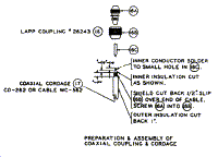 |
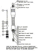
| Figure 32: Mast Base
MP-48-A, assembly with coaxial lead-in connection |
|
 |
 |
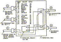
| Figure 33: Wiring
diagram of Radio Set SCR-193-( ) using terminal Block TM-183 |
|
d.) Notes.
(1) All screws, nuts, lockwashers, clamps, hooks, etc. ate in a heavy
cloth bag permanently and plainly marked. "Contents Hardware for Radio Set AN/VRC-1
installed in Truck, 1/4-ton, 4 x 4."
(2) Eight each Crystal Unit DC-11-( ) or CR-1- ( ) /AR are required to
complete equipment, for operation on the four pre-set transmitting frequencies and four
pre-set receiving frequencies provided for in the radio set. The radio set will operate
satisfactorily without a complete set of crystal units installed. The number of crystal
units installed in the transmitter and receiver determine respectively the number of
transmitting frequencies and receiving frequencies available for use at any time.
One each receiver crystal, frequency 8007.692 kc, and one each transmitter crystal
6450.0 kc are furnished for operation on a carrier frequency of 116.10 mc while one each
receiver crystal, frequency 8155.714 kc, and one each transmitter crystal, frequency
7010.0 kc, are furnished for operation on a carrier frequency of 126.18 mc.
Additional crystal units for use in the transmitter and / or receiver may be ordered by
specifying the carrier frequency of the signal it is desired to receive or transmit. The
number of crystals to be furnished per radio set should be specified by the requisitioning
arm or branch. Request for additional crystals should be submitted through channels
established by the air forces to the crystal bank of that air force.
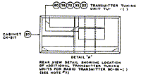
(3) If authorized, three auxiliary transmitter tuning units, in
addition to Transmitter Tuning Units TU-6-( ) and TU-7-( ), may be supplied with three
Case CS-48.
(4) The 24-pound mountings shall be substituted for the 12-pound
mountings normally furnished as part of Case CS-80-( ) and Dynamotor Unit PE-98-( )
because of the added shock load in vehicular installation.
(5) Capacitors shall he installed between the input brush terminals
and frame of Dynamotor Unit PE-98-( ) to suppress noise emanation. Method of installation
is indicated in figure 31, detail E
(6) The standard name plates of Case CS-80 and Dynarnotor Unit PE-98-(
) shall be stamped or otherwise changed to read Case CS-80-( )M and Dynamotor Unit PE-98-(
)M respectively, to indicate the modifications described in subparagraphs (4) and (5)
above.
19.) Assembly and Installation.
a.) Preliminary Check.
Truck, 1/4-ton, 4 x 4, ordinarily has a 6-volt electrical system. Radio Set AN/VRC-1-( )
requires 12 volts for operation. Kit, 12-volt Conversion, Truck, 1/4-ton, 4 x 4, supplied
by the Ordnance Department, must be installed in the vehicle, as shown in Modification
Work Order G-503-W-7, in order to supply 12 volts to the radio set. Additional items for
improving the suppression of the vehicular electrical system are provided with the
conversion kit. Make sure that the conversion kit has been installed in the vehicle before
installing the radio set.
b.) Procedure.
(1) Since Radio Set AN/-VRC-1-( ) is procured with its principal
components assembled in Cabinet CH-217, installation procedure is simplified. Place
Cabinet CH-217, in the rear of the vehicle and secure with the four brackets provided, two
on each end, as shown in figure 31.
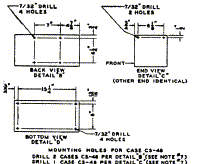
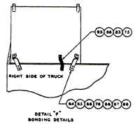
(2) In order to reduce radio noise interference caused by the
electrical system of the vehicle, Cabinet CH-217 must be bonded to the vehicle by means of
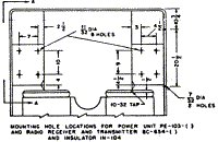
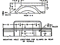
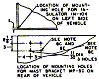
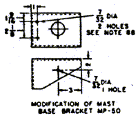
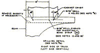
the provided bonding jurnpers, one on each end of the cabinet. Drilling details for the
necessary holes are shown in figure 31.
(3) The surfaces around the mounting holes at the point of
contact between the bonding jumpers, the cabinet, and the vehicle, should be prepared by
first removing the paint and cleaning the surface with sandpaper, a file, or emery cloth.
Then tin with solder. Shakeproof washers should be used between the bonding jumper in the
cabinet and between the bonding jumper in the vehicle, and the bolt securing the bonds
must be tightened firmly.
(4) Route Power Cord CD-260, to the vehicle terminal box as shown in
figure 31 and connect the positive and negative leads to the corresponding terminal in the
vehicle terminal box. Secure Cord CD-260 in place with the provided clamps and hardware.
c.) Installation of Mast Base MP-48-A.
Refer to figure 32 and install Cord CD-689 inside the mast base as shown. Remove item 9 in
order to observe that the tip of Cord CD-689 engages the slot, then replace and tighten
the screw. Screw adapter coupling, item 15, into the bottom of the mast base. Remove items
2, 3, and 4 from the bottom of the mast base. Install the mast base in the mast base well,
located in the top of Cabinet CH-217, and secure with items 2, 3, and 4. If coaxial
connector is not already attached to the coaxial cable, prepare the end of the cable as
shown in figure 32, and attach the connector to the cable. Connect the coaxial cord from
Mast Base MP-48-A to Radio Transmitter BC-625-( ) as shown in figure 31. When Mast Section
MS-53 is installed in Mast Base MP-48A, and a lower clearance height is desired, the mast
base may be flexed 90' and the mast section held in a horizontal position by pulling the
mast section down and engaging the mast section in the hook provided on the top center of
cabinet CH-217.
d.) Mast Base MP-57 and Mast Bracket MP-63.
Remove nuts and washers holding spare wheel on the rear of the vehicle and, using the same
nuts and washers, secure Mast Bracket MP-63 to spare wheel stud as shown in figure 31.
Refer to figure 8 and assemble Mast Base MP-57 as follows: Place item 1 over the hole in
the mast bracket. Place item 2 over item 1. Place item 3 over item 2. Insert item 4
through the hole in the mast bracket. Place item 5 over the flange of item 6. Insert item
6 upward through the hole in the mast bracket. Place items 7 and 8 beneath item 6 and
fasten entire assembly in place with items 9 and 10. Connect Wire W-128 as shown in figure
31.
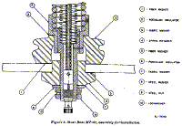
Figure 8: Mast base MP-57, assembly for installation |
|
e.) Stowage Items.
All. items, such as: Boxes BX-8, BX-21, Roll BG-56-( ), etc., that are listed in this
instruction as items to be stowed, shall be stowed at the discretion of the using arm.
Mast Rack FT-476 is provided on top of Cabinet CH-217 for carrying mast sections.
f.) Interfereence of Mast Section MS-53 with Vehicle Top.
A hinged arm is provided on top of Cabinet CH-217 to hold the vehicle top away from
Mast Section MS-53. This must be used to prevent contact between, the vehicle top and the
mast section when the very-high-frequency portion of the set is used while the vehicle top
is up.
 |
 |
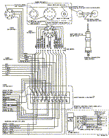 |
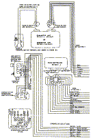
| Figure 34: Cording
and wiring of V.H.F. portion of Radio Set AN/VRC-1-( ) in Truck, 1/4 ton 4x4 |
|
Back to Installation of Radio Equipment in Truck, 1/4-Ton, 4 x 4 Index Page.
Army Radio Sales Co. Home Page. |


