By Ben Azari
Army Radio Sales Co. http://www.armyradio.com
Please Note: Army Radio Sales Co. and this Article's author are not responsible for any damages or personal injury whatsoever, that may occur as a result of information provided here. This Article is published in good faith and as far as we can tell accurate. Make sure you understand the instructions before starting. Modifications to military radio sets may invalidate the suppliers warranty and reduce the re-sale value of the radio.
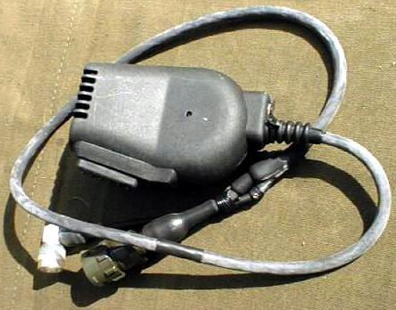
Many find the standard headset for the German SEM52A, VHF radio set uncomfortable to use. This modification will allow you to adapt the Clansman Speaker /Microphones which were intended for Couger Radio Sets to be used with the SEM52 Radio Set. This modification is easy to do, uses basic tools and involves no additional components.
The Clansman SP/Mic unit come with a Clansman 7 pin audio plug, which is the wrong type for the SEM52. Spare audio connectors for the SEM52 are hard to find. Unless you already have one, the standard SEM52 headset lead will have to be adapted for this purpose. This will not destroy the original headset beyond repair. If you do have a spare audio connector, then you will have to work out the connections yourself. Wire colour coding of your units may be different from the ones mentioned in this article.
Ear piece impedance of the SEM52 headset is 150 Ohms, and the speaker in the SP/Mic unit is 8 Ohms. In this article I have connected them directly together. On full volume it can get very loud. You can restrict that by adding a 47 Ohm resistor in series with the speaker. +9VDC is present on the audio cable of the SEM52 and it is used to power the microphone circuit of SP/Mic unit.
Finally read and understand all the instructions before attempting this modification, or you might end-up with a Dead Radio (blown fuses or worst). Happened to me a few times, while working this out.
Tools Needed:
1) Soldering Iron and some Solder.
2) A small Phillips Screwdriver.
3) A small Flat Screwdriver.
4) Side Cutters.
 |
| Clansman Speaker / Microphone Circuit
Diagram and Modifications Please Note: Points (A) to (F) on the circuit refer to marking on the SP/Mic units PCB and not the SEM52 Connector Pins. Indicated colours refer to SEM52 audio cable wires. Your wires colour coding may be different from the ones shown. |
Step 1 ) Preparing the Clansman Speaker /Microphone
Un-screw 4 Phillips screws from the back of the SP/Mic unit, and pull off the back cover.
Cut the shielded wire which goes to the antenna socket as close to the socket as possible.
Leave the socket in place if you don't want a hole. Clear out the rubber sealant around
the wires, then "Only" pull off 6 wires which go to the main cable harness.
Un-screw cable harness strain relief screw and remove the cable harness from SP/Mic unit.
Remember only pull off the wires which go to the cable harness, leave all other wires alone. Looking at the circuit of the SP/Mic unit, you will now have to cut 2 wires, Points A-B and Points C-D, and re-connect them to points C and E. The table below should explain how.
| Cut Between Points C-D. | Un-solder Red wire from pin on the PCB and note it's position. |
| Connect Points D to E. | Connect the free end of the Red wire to pin ( B ) on the PCB, (PTT/Ground). |
| Cut Between Points A-B. | Cut White wire going to PTT Switch, as close as possible to the PTT Switch as you can. |
| Connect Points B to C. | Connect the free end of the White wire to the pin that the Red wire used to be on. (Pin between the screw and point E on the PCB). |
Step 2 ) Preparing of the SEM52 Headset cable
Un-screw 4 screws holding the cover of the PTT Switch box and remove the cover.
Draw and write down the wire colour coding of the PTT switch box. Carefully unsolder 7
wires which go to the audio connector, do not cut the wires or the main cable from the PTT
switch box. Remove the audio cable from the PTT switch box. Replace the cover and put away
the headset and PTT switch box with your drawing for future use.
 SEM-52 Headset wiring diagram. Connector pins viewed from pin side |
Step 3 ) Joining of the SEM52 Headset Cable to the Clansman Speaker /Microphone
By now you should have the SEM52 audio connector with cable and the modified
SP/Mic. Pass the wires of the connector cable through the hole that the old cable used to
go through.
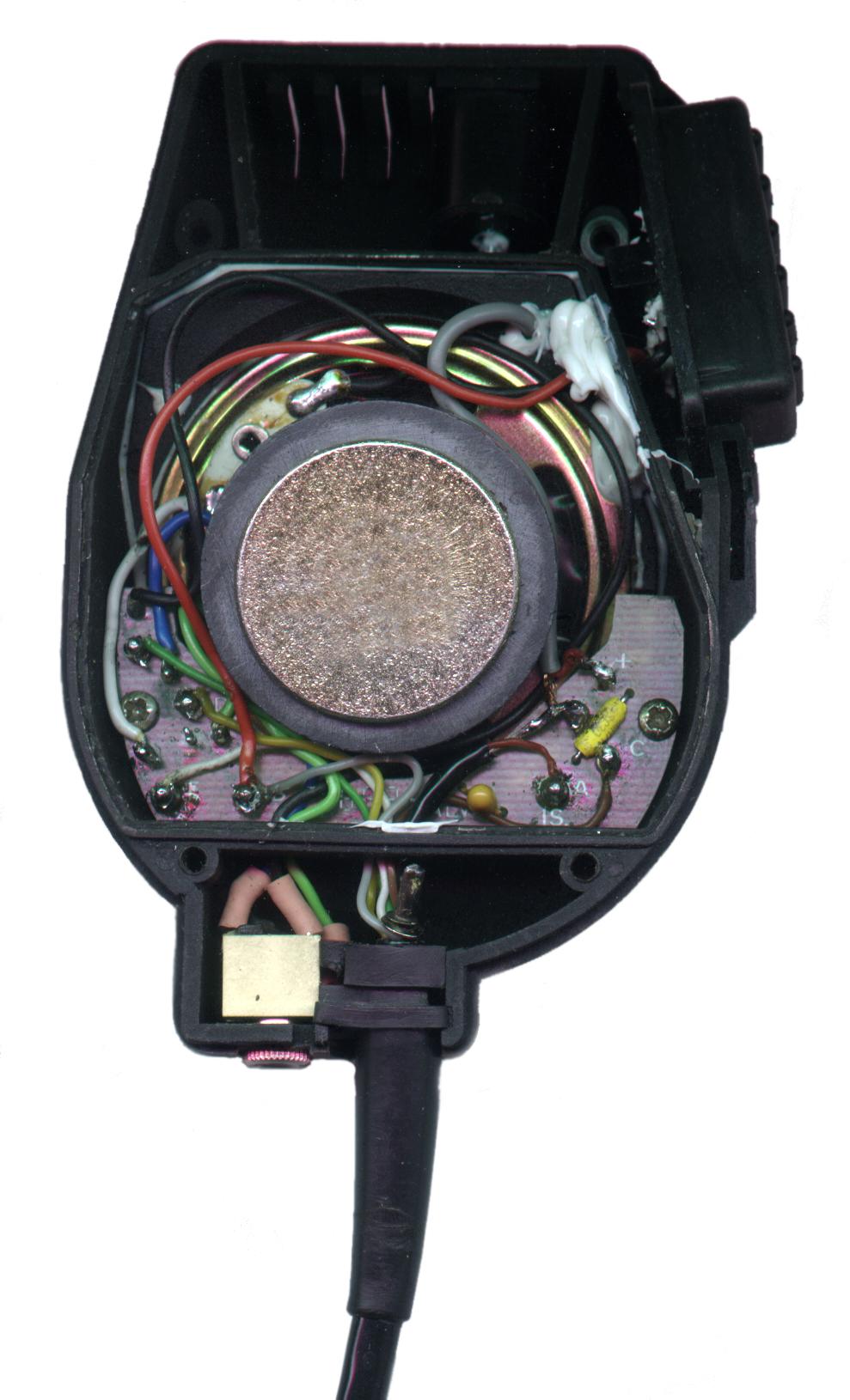
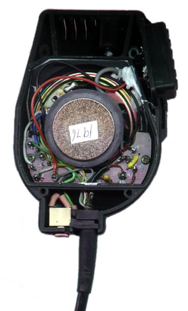 Inside of the modified unit See Very Big Picture |
|
Solder shield of the microphone cable to the shield of the microphone on
the PCB, indicated by "-". Solder centre of the shielded microphone wire "Red" to, pin (A). Solder +9VDC wire "Brown" to pin (C). Solder speaker wire "White" to pin (E). Solder speaker wire "Yellow" to pin (D). Solder PTT/Ground wire "Grey" to pin (B). Solder PTT wire "Green" to pin (F). Tidy up the wires and push in the cables rubber strain relief between the phone-jack socket and side of the SP/Mic unit. Re-check every thing thoroughly, you don't want a dead radio. |
Speaker / Mic |
SEM 52 Audio Cable Pin Label |
SEM 52 Audio Connector Pin-Outs |
|
| Pin ( D ) | A | Yellow | Ear Piece ( Speaker ). |
| Pin ( E ) | B | White | Ear Piece ( Speaker ). |
| Pin ( A ) | C | Red | Microphone, centre of the shielded wire (Microphone Out ). |
| Pin ( F ) | D | Green | Push To Talk Switch ( PTT ) |
| - | E | - | Unknown and not used. |
| Pin ( C ) | F | Brown | +9VDC for Powered Microphone ( +9VDC ) |
| Pin ( B ) | G | - | Microphone Cable Shield. ( PTT / Ground ). |
| Pin ( B ) | G | Grey | ( PTT / Ground ). |
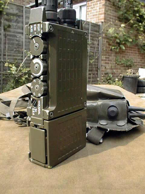 The German SEM-52 |
|
Step 4 ) Testing. You will need another radio set-up on the same frequency as the SEM52. Connect antenna and the new audio cable to the SEM52, turn the volume knob half way, and turn ON the radio "EIN". If all is well you should hear normal radio noise from the speaker. Turn Up/Down the volume control, and the noise should go up and down accordingly. Push in the PTT switch and noise should stop, release it, noise should come back. If it didn't you have blown the Fuse, "Re-check the wiring and replace the Fuse". Push in the PTT switch again to test the microphone. Good clear signal should be heard on the other radio set. If all is well, the back cover of the SP/Mic unit can now be installed. To resist water damage you could re-seal the unit with rubber sealant, as it used to be. |
Visitors to this page since 28 December 2000
Back to Your Articles Index Page.
Army Radio Sales Co. Home Page.