|
|
|
|
|


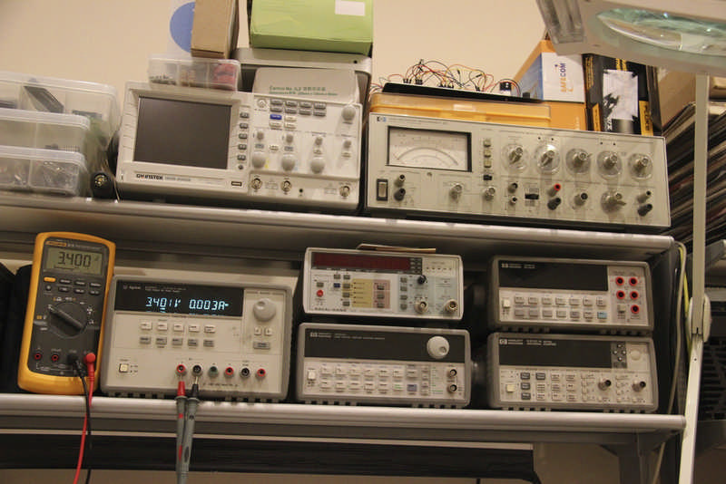
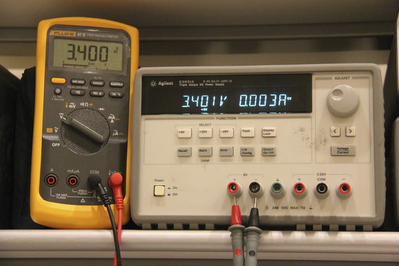
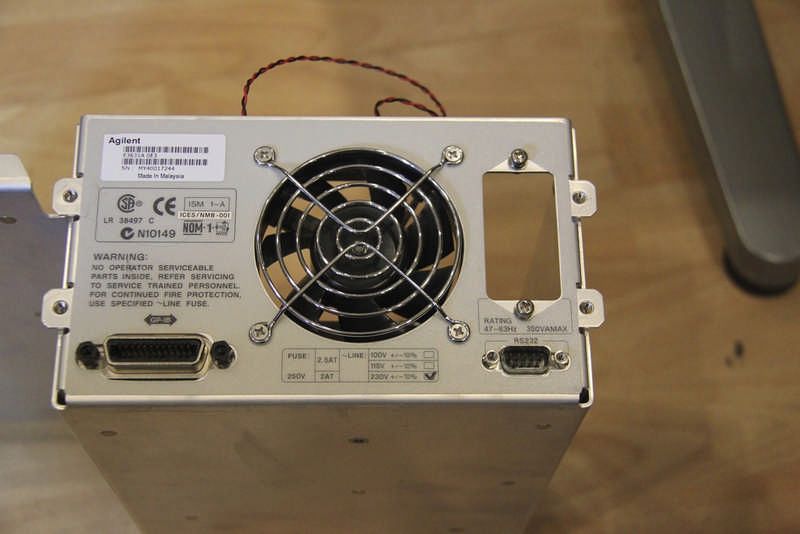
I recently bought a faulty Agilent E3631A bench power supply on e-bay which I thought would be a nice addition to my *slightly excessive* electronics hobby workbench. These power supplies are really nice; they are engineered and built like military equipment, good high quality materials and mechanically very robust. An great indication of how good these things are is the second hand values, these things cost $900-$1000 to buy in reasonable condition so they are not cheap. I bought this particular one faulty and thought I would have a go at repairing it.
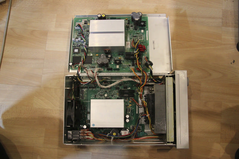
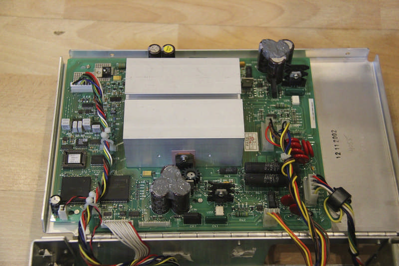
My first impression of the electronics in side was not great, it seemed very seriously over engineered for what it was trying to achieve. It seemed like the designers had a field day adding all sorts of crazy circuits because they could. The ADC is made up of discrete IC's, there is a custom logic chip in there as well as a CPU, ROM and RAM, there are numerous power supplies for bias and control circuits all floating around each other and most things seemed much more complicated than they need to be. The one real surprise though was the opto isolation in the analogue domain. The CV and CC reference signals from the DAC for the +6v supply are isolated through high linearity opto couplers type HCNR200, this is something that would be crazy to do today when the cost of micro-controllers are so low and have all the goodies like DAC' ADC's and PWM's making isolation in the digital domain a far more sensible design choice.
|
|

In fairness though, I was making my initial judgements based on what's possible with today's components, things were very different 20 years ago so given its age it's a pretty sophisticated piece of kit really. Once working it does appear to work very well so my initial thoughts are not really founded on anything other than my own instinct to want things to be easier to understand and better as a result.
On with the repair.
First things first, after a quick check of the obvious big components like the series regulator transistors etc, I very quickly needed a schematic diagram. Agilent were less that helpful here, the manuals they put out now days specifically have the detailed schematics removed from the documents despite there being a reference to them in the index. When I contacted Agilent and asked for a schematic I was told in no uncertain terms (after a 4 day response time) that they no longer make the schematics available, but they do offer a £450 exchange repair service, come on HP/Agilent, by all means offer the service but don't stop those of us who want to hack around from doing so. The solution was to buy an original printed service manual which did include the schematics; e-bay and $10 got me what I needed. As luck would have it, while waiting for the manuals to arrive in the post, I also managed to find a manual on the net which still had the schematics present, not from any official Agilent source I might add.
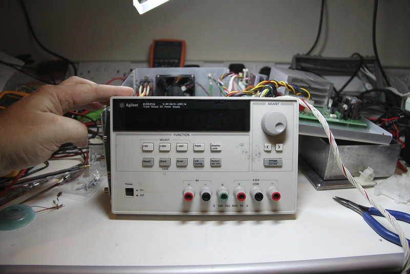
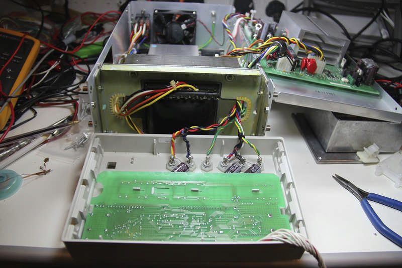
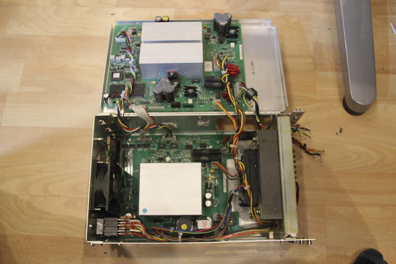
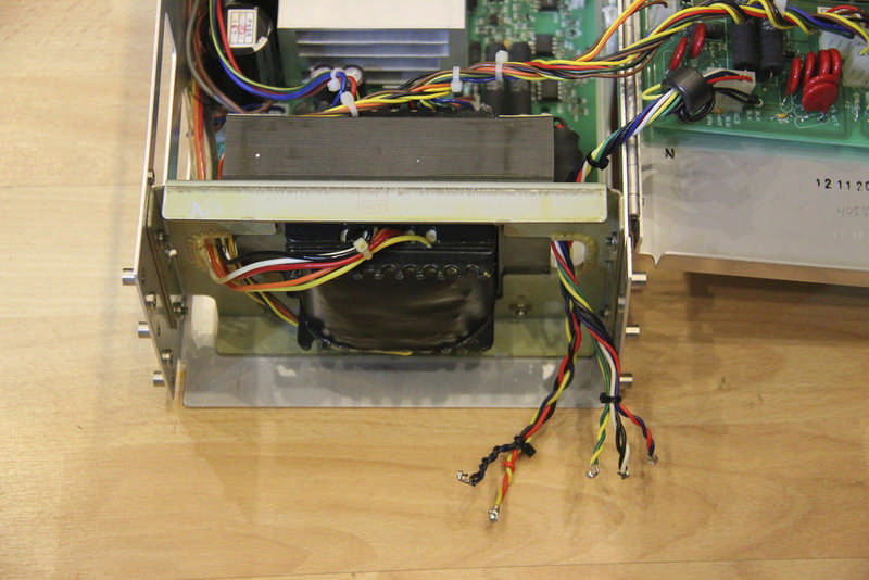
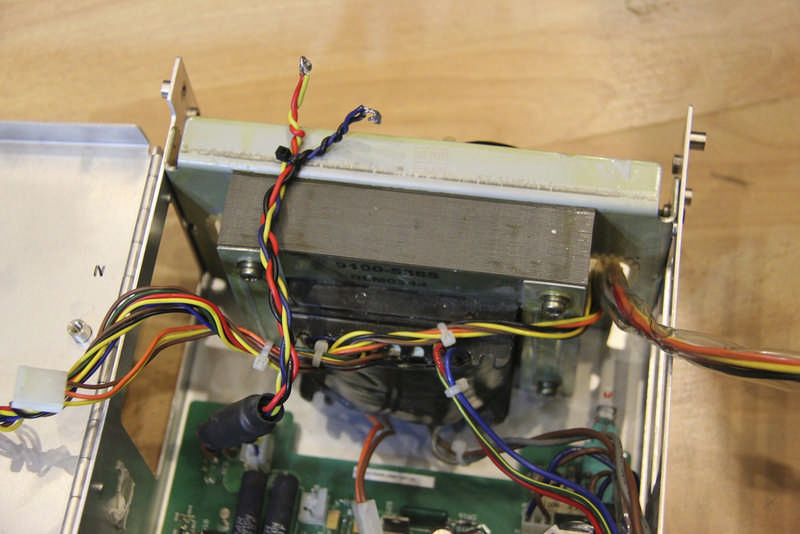
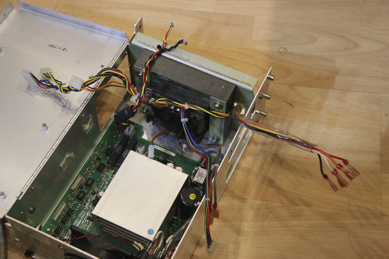
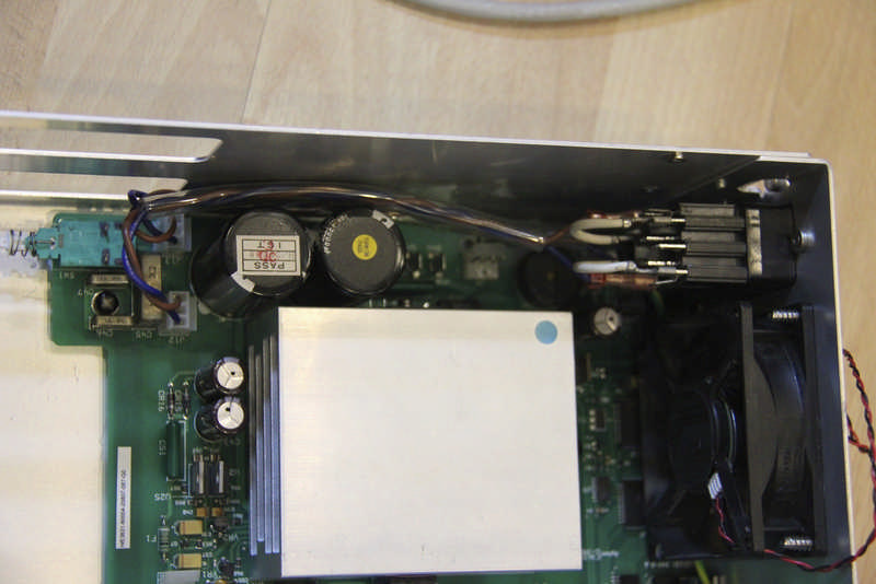
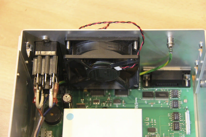
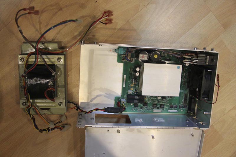
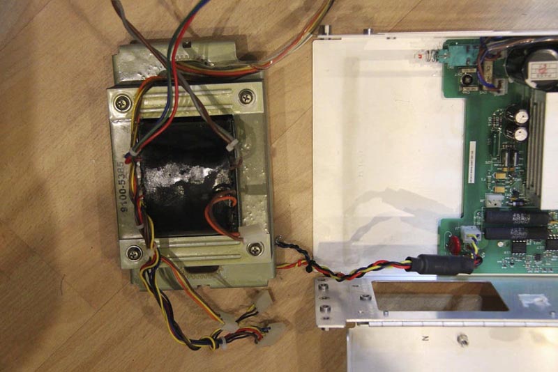
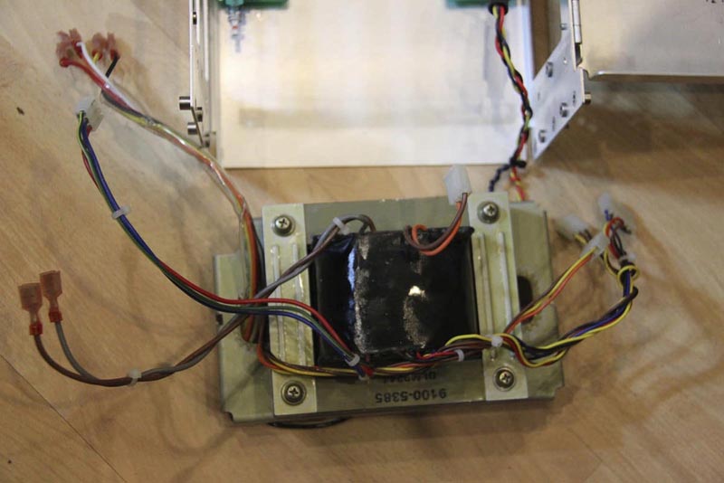
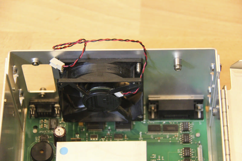
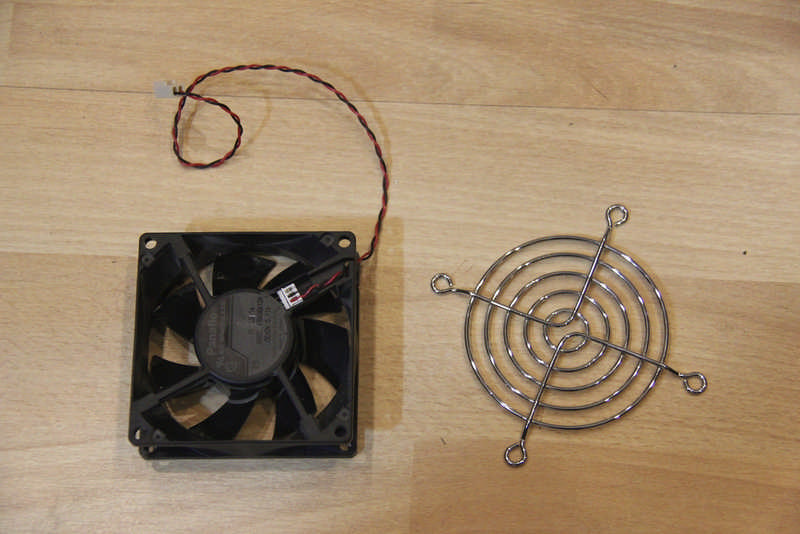
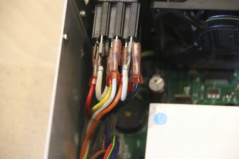
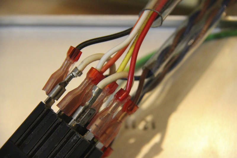
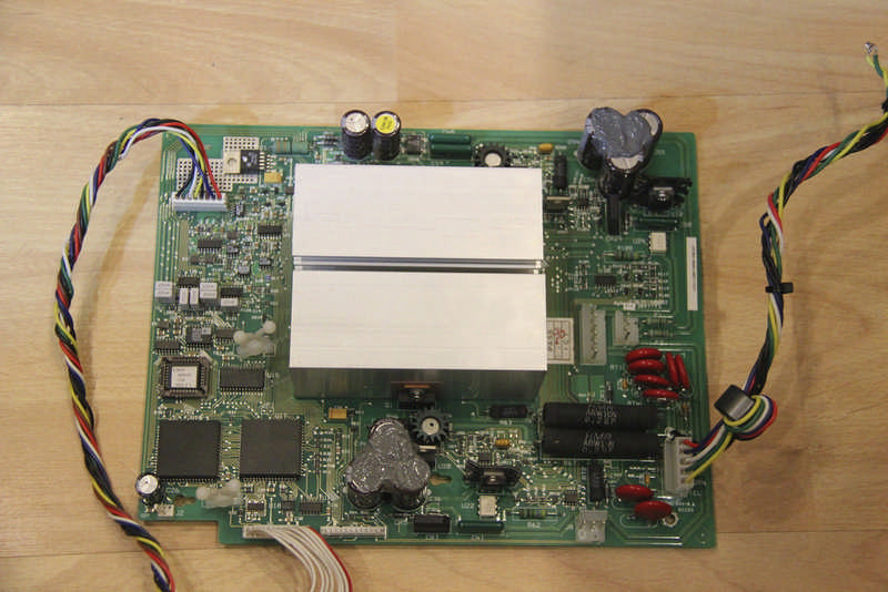
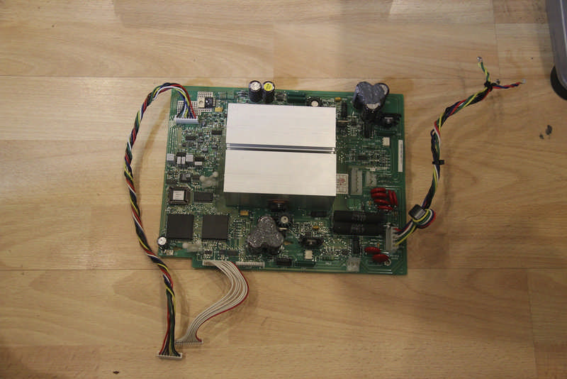
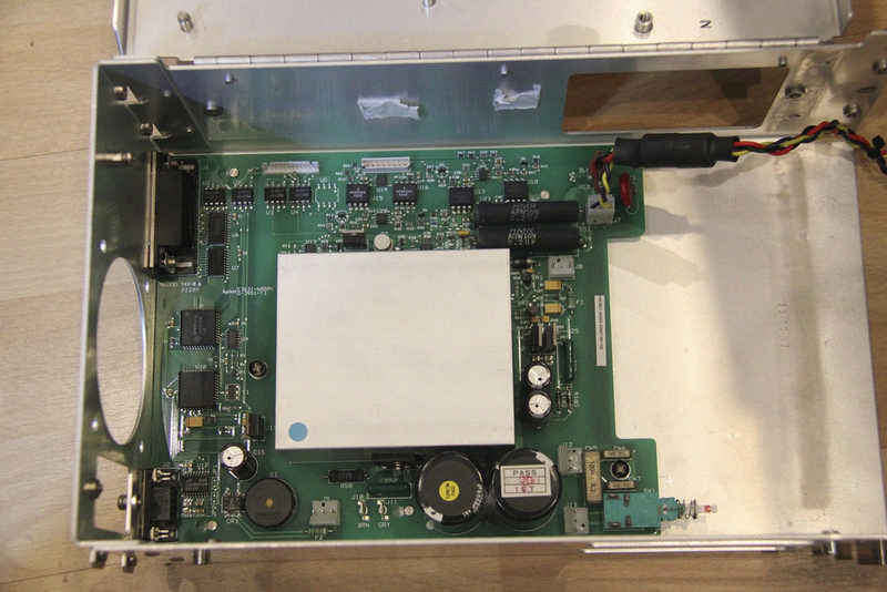
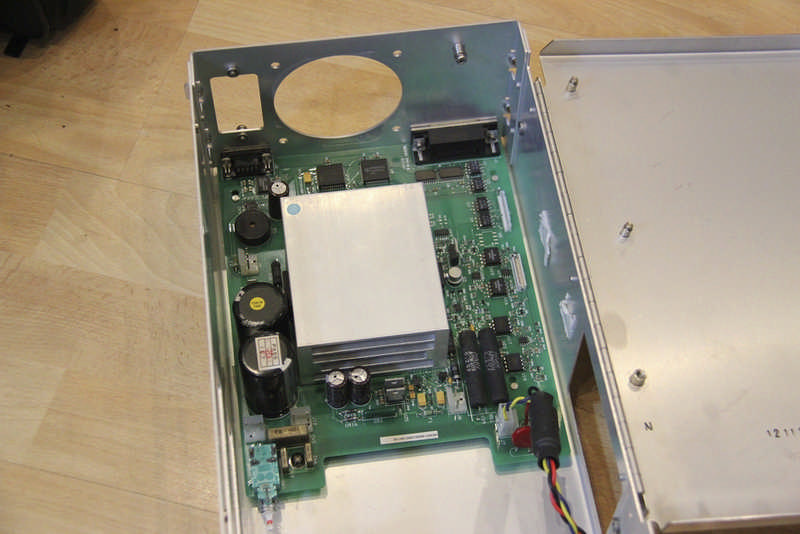
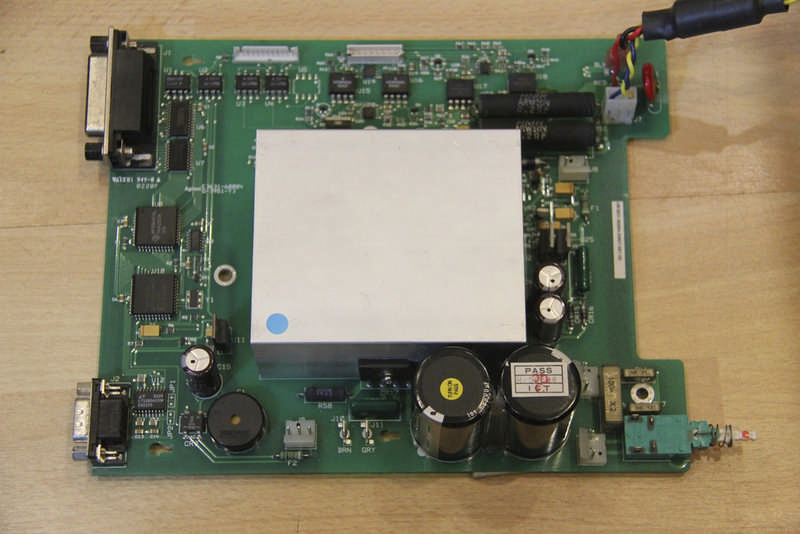
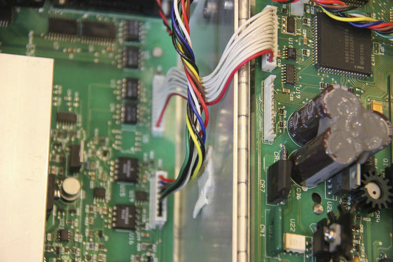
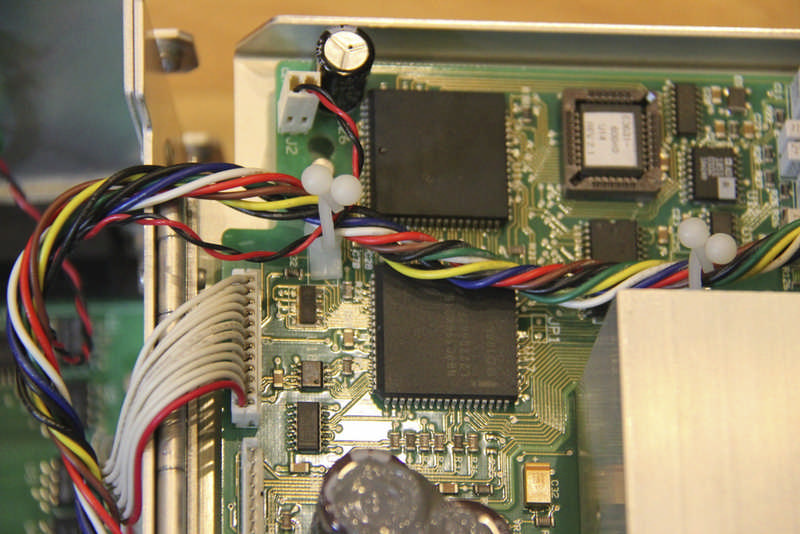
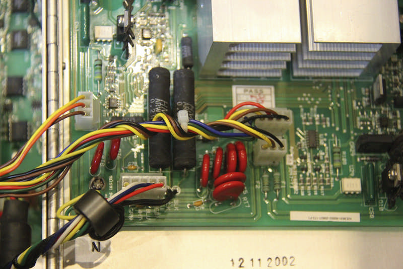
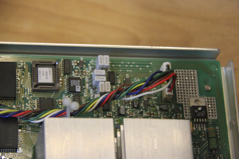
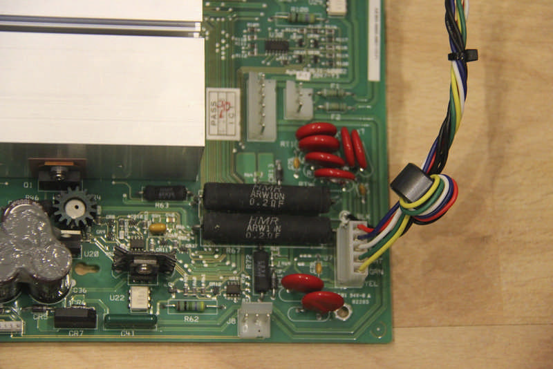
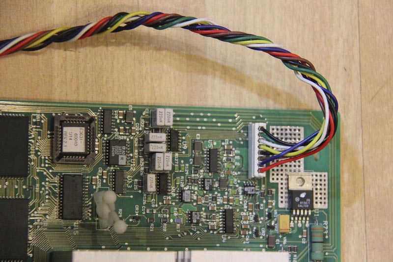
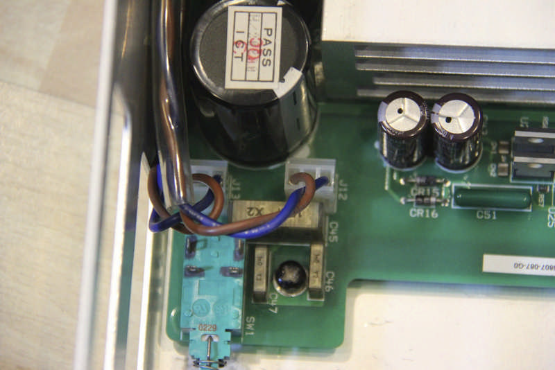
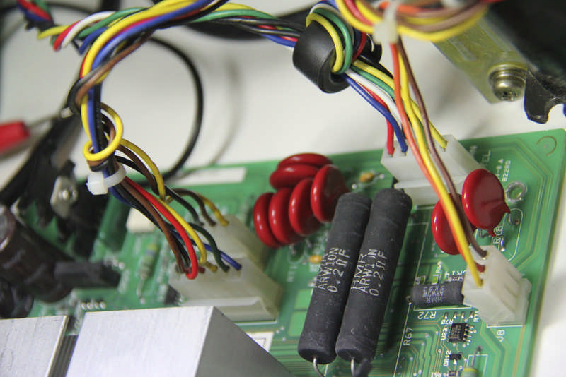
I set out to work on fixing it and found I had to strip it down completely, removing the two boards, front panel, transformer and wiring from the chassis and spread it out on the bench. If you find yourself needing to repair one of these, be prepared to commit serious bench space to the exercise. I have taken a bunch of photo's if the teardown so you can see what all the bits look like.
 |
|
 |
|
 |
|
 |
|
|
||||||
 |
|
 |
|
 |
|
 |
|
|
||||||
 |
|
 |
|
 |
|
 |
|
|
||||||
 |
|
 |
|
 |
|
 |
|
|
||||||
 |
|
 |
|
 |
|
 |
|
|
||||||
 |
|
 |
|
 |
|
 |
|
|
||||||
 |
|
 |
|
 |
|
 |
|
|
||||||
 |
|
 |
|
 |
|
 |
|
|
||||||
 |
|
 |
|
 |
|
 |
|
|
||||||
 |
|
 |
|
 |
|
 |
There were various faults with the PSU, numerous op amps and some CMOS logic IC's were faulty as well as two open circuit 33k resistors. At a guess I would say there was some kind of big static or high voltage discharge into or across the outputs that caused the original fault. I had to isolate the various areas of the circuit and work on them individually, making assumptions about what should be present in terms of voltage levels and feed in lots of external signals to get to the bottom of each fault.
I struggled with the configuration of some of the analogue circuitry, fortunately for me I have a good friend who understands much more about analogue electronics than I do so some exchange of e-mails and sections of circuits with measurements kept me on track and expanded my own knowledge too, cheers Span.
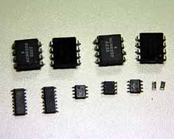
Here are all the components I ultimately had to change.
While fixing it I also managed to introduce some faults of my own. Specifically I managed to blow two of the HCNR200 opto couplers, easily done just with a slip of a multi meter probe shoring out pins 2 & 3 puts 15v with no current limit straight into the internal LED rendering it open circuit instantly. I managed to blow four of them like this before I figured out what I kept doing, doh!
After working through these problems I finally got it working except when placing a dummy load on the +6 output, the voltage I was measuring went up! A bit more inspiration from my friend Span and a scope on the output and voila, it was bursting into oscillation under load, probably due to the 4 ohm wire wound load resistor. It turned out this was down to the fact that the electrolytic capacitors soldered onto the back of the binding posts on the front panel are actually there for stability reasons, obvious once you know. I had removed the output wiring from the front panel to make it easy to work on. Strapping 1000uF across the output solved the problem.
Having worked on this I have been inspired to have a go at designing my own programmable PSU from the ground up to see if I can match the specs but use more modern components and design approach, I will post info on progress if I get around to it.
Visitors to this page since 18 May 2012
Back to Your Articles Index Page.
Army Radio Sales Co. Home Page.