By Joe Bell G4PMY Owner & Operator Of an R161-A2M
E-Mail jbell@bellradio.co.uk
Joe Bell's Web Site
Russian to English Electrical / Electronic Dictionary
This Dictionary is
compiled By Joe Bell G4PMY and has many useful
Russian radio terms with their English translation. To read this document you
need to download and install the free Acrobat
Reader® software, you can then view and print Adobe PDF files.
|
Click Here to Read The Dictionary |
 Click Here to Download Acrobat Reader |
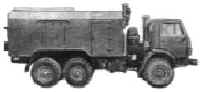
ZIL Radio Truck
In October 1999 I purchased what was advertised as a “Zil Radio Truck”. This
ten tonne Russian military communications truck appeared to be well equipped and
constructed with reasonable quality, contrary to military doctrine handed down to me
whilst in service.
The MoD decided not to release any of the documentation they had received with the truck as many of the topics dealt with therein were still officially classified secret. Nor would they provide any history relating to where this truck came from.
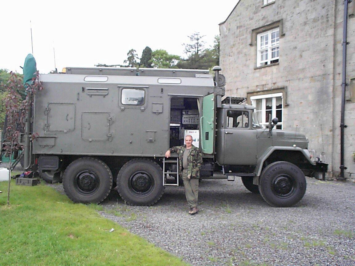 Joe Bell and The ZIL Radio Truck |
The original truck was powered by a V8 petrol engine which developed 150 HP at 3000 RPM. This specification is the same as all other Zil 131 trucks and probably works just fine in the cargo version which weighs only two tonnes or so. The power delivery at ten tonnes was to-tally inadequate for European roads and traffic conditions, and so half way through this years show season I swapped the petrol engine for a B series Cummins diesel with an Eaton six speed box. Following a number of show events, those members of the MVT and similar organisations who also had an interest in radio frequently contacted me for more information relating to this truck, and some of the radio sets employed. Although I have put info onto my web site the requests keep appearing. I decided that the VMARS news letter may be a good platform to publish the next round of information. |
The radio station is actually known as an R161. This number in fact relates to a series of trucks and equipment designed to provide a variety services. The large 161 stations are carried on no less than three trucks and have a staggering 15Kw RMS Tx power output. The first section of the following article deals with this larger system. The information has been translated from Russian without too much grammatical correction, and so it may not read as it would if written from English.
The purpose of the larger systems is to provide a communications backbone into which smaller and lower power stations can if needed “Subscribe”, although the smaller stations are capable of operating independently.
The Subscriber stations are designated R-161-A2M and it is the latter which I obtained, and hence I am able to produce much more detail. I do not intend to discuss frequency hopping or encryption, nor do I intend this article to be technical in any way, it is simply a description of a Soviet communication system for which nothing was previously known outside of the USSR and latterly the MoD.
 |
|
 |
|
 |
Automated Adaptive Mobile H.F. Radio Station
Intended for setting up automated adaptive noise- immunity HF radio links providing
communication over 3000 Km to 4000Km with a frequency range of 1.5Mhz to 59.999 Mhz.
This frequency agile radio system provides the three goals of frequency hopping radio, these are 1, resistance to jamming, 2, resistance to direction finding, and 3, resistance to intercept. The transmission of telephone, telegraph, and data is assured under high random or intentional noise levels. Provision of a communications link is automatic, and will automatically adapt to the noise environment. The remote control of the transmitter vehicle is provided from the receiving vehicle.
The radio station consists of three equipment shelters or Kungs, carried on the truck chassis. The receiving shelter and the transmitting shelter are carried on a Ural 43203 chassis. The generator set is carried on a Kamaz 4301 chassis, and is intended to provide power to the transmitter unit only.
The shelters have heating and cooling systems built in to ensure the correct and comfortable environment for the operatives. There are two radio relay sets being part of the equipment carried. The radio relay is used to control the transmitting vehicle from the receive shelter (up to 25Km). The control link can also be made by data cable (up to 10Km). The trucks are also fitted with HF radio for communication whilst travelling in column.
These trucks provide the “Back-Bone” communications network for smaller 161 stations to act as “Subscriber” stations. These smaller units are describer later on.
Specifications and General Characteristics of Radio Station |
|
| Time to establish communication at 0.9 probability | 50 Seconds |
| Communication probability factor at any time /season | 0.8 |
| Number of pre-set frequencies | 10 |
| Adaption type | Frequency two step |
| Number of sub frequencies in adaption second step | 15 |
| Sub frequency adjustment time | 2 Seconds |
Operating Modes |
|
| Single channel SSB telephony on USB or LSB | A3J |
| Each telephone band 300hz to 3.4Khz | A3A, A3J |
| Two channel SSB telephony with transmission of same information on USB and LSB | |
| FM telephony | 3F |
| AM telephony | A3 |
| Amplitude telegraphy | A1 |
| FSK telegraphy | F1-200 |
| At a rate of 200 baud | F1-500, F1-1000 |
| Double shift FSK telegraphy | F6-200, F6-500 |
| Distance between Rx and Tx truck | |
| When connected by cable, up to | 10Km |
| When connected by radio relay, up to | 25Km |
| Frequency spectrum spacing | Hz 100 |
Transmitting Vehicle Specification |
|
| Radio Transmitting Power | 15Kw |
| Transmitter non linear distortion (2 tone method) | -30dB |
| Relative frequency instability during 24 hours | 2x10⁻⁸ |
| Time to adjust transmitter to frequency with 20 channel storage ability | 2 sec |
| Time to re-adjust tx to any | 2 sec |
| Fitted with power and travelling wave meter | Yes |
Receiver Specification |
|
| Radio receiver sensitivity in telegraph mode | 0.5uV 12db |
| Receiver frequency range | 1.5 to 60Mhz |
| Double conversion | Yes |
| Antenna switch | Yes |
| Automatic mode switching | Yes |
| Time to readjust rx to any frequency | 0.35 sec |
Terminal Equipment |
|
| Telegraph Set | STA-8 |
| Morse code sender | R-020 |
| Morse key and telephone sets | 1 |
| Modem for digital telephone and telecode at 1200/2k4 baud | AT-3004D |
Radio System Power Supply |
|
| Three phase | 2x 30Kw 380 Volts |
| Power consumption of transmitter vehicle with life support | 39Kw |
| Power consumption of transmitter vehicle without life support | 30Kw |
| Power consumption of receiving vehicle with life support | 11Kw |
| Power consumption of receiving vehicle without life support | 4Kw |
Climatic Operating Conditions |
|
| Radio Station operating ambient | -40 to +50c |
| Tolerable humidity | 98% |
| Maximum altitude ASL | 3000 m |
| Weight of each vehicle | 13,450 Kg |
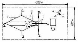
| Antenna Configurations, Receiving |
|
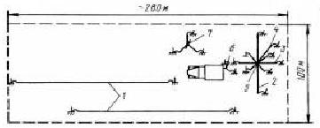
Antenna Configurations, Transmitting | ||
|
|
|||
| 1 | Travelling wave antenna | 1 | Slant rhombic | |
| 2 | Vertical semi-rhombic | 2 | V antenna | |
| 3 | Slant wire dipole | 3 | Vertical double rhombic | |
| 4 | Sloper | 4 | Radio relay antenna | |
| 5 | 3m rod, 6-10m rod | |||
| 7 | Radio relay antenna | |||
 |
|
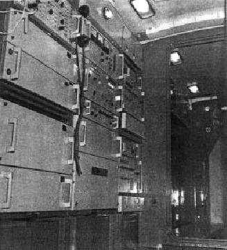 |
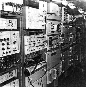
| Internal Views, left RX cabin right TX cabin | ||
Radio Station R161-A2M
The R161-A2M is a smaller version of the R161-5 series and is contained in a single
shelter or Kung transported on a Zil-131 chassis. The A2M version is also equipped to
provide automatic noise immunity HF communications. The method of achieving noise immunity
is frequency hopping.
The Kung is divided into three rooms. The rear most room is equipped with a 16Kw three phase petrol driven generator. This generator is vented with air intake and hot air exhaust via opening panels in the side of the truck.
This room also contains two large blower motor fan assemblies used to keep the main radio amplifier cool, and a 3Kw forced air cooled dummy load. The room also contains a mains input filter used when the truck is plugged into mains power available at workshop or other buildings, and a 30 amp battery charger used the charge the auxiliary batteries.
 |
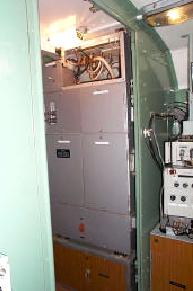
The main generator. The large grey box on the lower right is the
blower cabinet, and the smaller grey box above is the dummy load. Also seen in this picture are two fishing rod style rests above each door. These rests are used to stabilise the tactical whip antennas when they are lowered to slopping position when travelling through trees. To the extreme right of the picture can be seen one of the sixty foot telescopic masts used to support most of the antenna arrays. |
 |
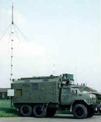
Photo shows the truck deployed using the VHF broad band dipole.
The cool air in-take for the generator can be seen through the open door. On the roof of the truck can be seen two lockers used to store all of the antenna equipment's. Over the drivers cab can be seen the petrol burning central heating system and mush-room ventilator together with the biological weapons filters. |
The centre room of the Kung houses the twin power amplifiers, and the twin antenna coupling units. The frequency split for both units is 30Mhz, and selection of the correct amplifiers and coupler combination is achieved automatically from the main operating console.
 |
|
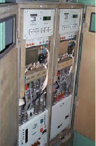 |
| The coupling cabinets | The twin power amplifiers |
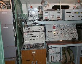
The forward room of the Kung contains the main operating console. This is equipped with two radio receivers, one Tx exciter, one frequency hopping control unit, one frequency hopping modem, one antenna tuning control unit, and the main console for selection of signal routing and antenna selection.
 |
|
 |
| General view of the main console and equipments | ||
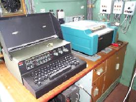 |
To the left can be seen the automatic Morse encoder / decoder and its associated teleprinter. The units are of East German design and manufacture. The are capable of 12wpm to 50 wpm. The system can also select transmission with or without hard copy. |
 |
|
 |
| Receiver designated R160P | Exciter unit designated “Lazure” |
Above top left can be seen the main receiver designated R160P. This receiver is of modular construction, nuclear hardened and all solid state. There are multiple connectors at the bottom of the receiver. Two connectors are used to enter frequency programming data when the set is switched to remote control. This programming takes the form of a diode matrix located elsewhere in the system. One connector is used to rout audio from the receiver to various external equipment's, including loudspeaker, keyboard decoder, and modem. The receiver is multi-mode and includes AM, FM, USB, LSB, ISB, FSK, FFSK modes. There is a single aerial input on a coaxial lead, and the other coaxial leads permit the input / output of the 5Mhz internal frequency standard. These outputs are used in conjunction with the receivers frequency hopping capability. One unusual feature of the receiver, is that during system antenna tuning the receiver forms a balanced bridge with the exciter and selected antenna. The antenna tuning controls are then adjusted for a maximum dip in the meter reading. By using the exciter output which is only 10mW, antenna tuning can be undertaken without giving your position away during set up, or periods of receive only activity.
Top right can be seen the exciter unit designated “Lazure”. This is also nuclear hardened and of modular construction. Fully solid state and equipped to provide “noise adaptive communication” [ frequency hopping ] these radio sets are among the latest technology seen from the USSR. The connector pattern seen on the receiver is repeated on the exciter and provides the same functionality. Both sets can be seen above with their associated power supply units, which are in fact the same unit providing commonality of spares. The internal modules are also common to both sets. Those inputs and outputs appearing on modules which are used in the exciter but not in the receiver are simply terminated by dummy load. This practise suggests considered design during conception.
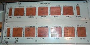 |
The peg-board used to program the ten pre-set frequencies. This peg-board is found under the writing surface at the main console. |
 |
|
 |
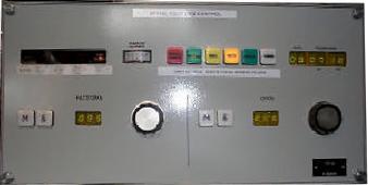
| Manual access and control for the antenna tuning | Noise adaptive controller [ Frequency Hopping Control ] |
Top left can be seen the manual access and control for the antenna tuning. The unit is equipped with ten memory locations where favoured settings may be stored. Also presented are SWR alarms and trip resets, plus control over either “working” or “tuning” states of operation.
Top right can be seen the noise adaptive controller [ frequency hopping control ]. Designated the R016 this unit interfaces directly with receiver and exciter taking direct control over their operating frequencies. The controller utilises the main or base frequency set by the operator, and then uses ten sub frequencies to form the selection of frequencies to hop to. During frequency hopping the net synchronisation is achieved by data exchange between all sets suitably equipped and forming part of the net. The writer believes that the hopping rate is about 2 per second , but it is not known if the hop pattern is orthogonal.
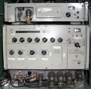
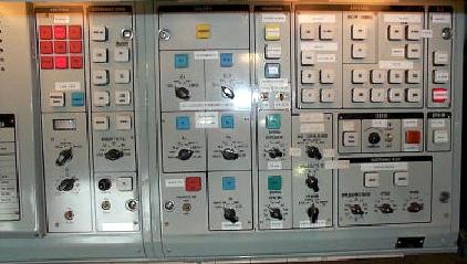 Main control panel |
Left can be seen the main control panel for the whole system. The red lights on the top left are alarm enunciators for frequency lock, blowers, overloads etc. The centre panel provides operator control over audio routing. Top right provides selection of antenna. Bottom right are the tuning control for the roof mounted active HF antenna. Other control deal with the radio power amplifiers and peg board frequency selection when using remote control. |
The system permits single frequency simplex working, split frequency simplex working, and split frequency duplex working. The cover which is just in view on the far left covers an audio and system patch field. Suitable interconnection within the patch field will permit re-broadcast operation, and telephone to radio transfer ( telepatch ).
The truck may be deployed as a long term communication station providing radio and telephone communications between the rear and forward units. In its long term role the two sixty foot masts would be demounted and set up in the field using the steel guy ropes supplied.
The diagram below gives an indication of how the system would be set up with priority given to either HF or VHF working. In HF priority working the VHF Tx antenna would be a broad band dipole complete with built in ground plane. The VHF Rx antenna would be a wire connected via a balun then coaxial cable to the receiver antenna switch.
In VHF priority mode, the VHF antennas for both Rx and Tx are replaced with log periodic antennas. In both modes the HF antennas are 400 ohm terminated rhombics with the exception of a single 13m wire dipole. All HF aerials are fed using ladder feeder.
 |
|
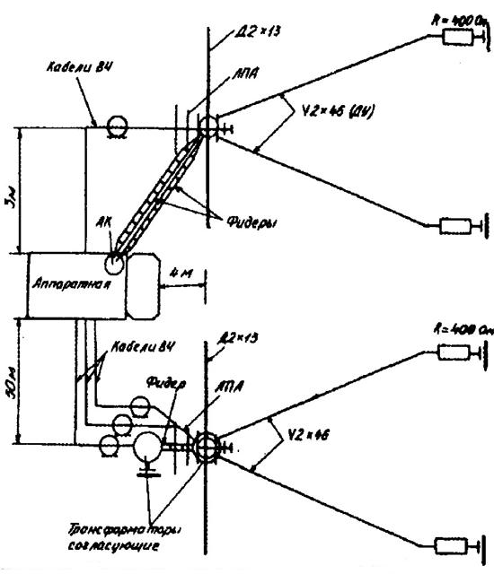 |
| HF and VHF antenna configuration diagrams | ||
R161-A2M Specification |
|
| Frequency range | 1.5 to 59.999Mhz |
| Transmitting power output | 1.5Kw RMS |
| Modes of operation | AM, FM, SSB, ISB, FSK, FFSK |
| Communication range (on site) | 2000 Km |
| Communication range whilst moving | 350Km |
| Set-up time on site three man crew | 1 hour |
| Set-up time mobile | 50 Seconds |
| Second electric generator | EU-131-8-T/400 8Kw PTO driven |
| Main electric Generator | EU-A-16-P/400 16Kw Petrol |
| Truck chassis | Zil-131-H |
| Gross weight | 9.53 Tonnes |
| Adaption Type | 2 frequency step |
Antennas |
|
| Rhombics | 2 off |
| Dipoles | 4 off |
| Log Periodic | 2 off |
| Broad Band Dipole | 1 off |
| 3 Meter Tactical Whips | 2 off |
| 4 Meter HF Whip | 1 off |
| Active Antenna 1 to 14 Mhz | 1 off |
 R326M Receiver |
Left can be seen the R326M continuously tuneable receiver. Because the main receiver is tuned to frequency by decimal switches, search tuning is made difficult and time consuming. The R326M is provided for just that purpose. When the desired net is found, the information appearing on the 326’s digital readout is transferred to the main sets, and netting begins.... |
I hope you have enjoyed reading about the R161-5 series. The content represents twelve months of research conducted mainly over the internet.
By Joe Bell G4PMY, A Member Of The Vintage and Military Amateur Radio Society, (VMARS).
Visitors to this page since 10 December 2000 Last updated 03 January 2003
Back to Your articles Index Page.
Army Radio Sales Co. Home Page.