
By Ray Robinson
VK2ILV
E-Mail robinson@srsuna.shlrc.mq.edu.au
The B-29 receiver (also known as a CR200) is a low frequency receiver for submarines and covers the frequency range 15 kcs to 550 kcs in 4 bands. It was built in the United Kingdom by the Marconi Wireless Telegraph Company. The CR100, CR150 and CR300 look similar, but cover HF bands. The brass identification plate reads Type B-29 Admiralty PATT. W2698 Ins No. 150674 (with a line through it) R/FR No. 23 1949.
Performance
The receiver is easy to use. When tuning across the bands, the aerial switch is set to
STANDBY. When you have found a station to listen to, switch to TUNE and trim the aerial
with the control. There are plenty of beacons, but not much else except the bottom edge of
the broadcast band, so finding anything but CW in these bands is a challenge. The BFO is
easy to use, and CW can be copied readily. The 1 kc filter gives a funny pipe sound when
switched in, but seems to function well, as it certainly removes all adjacent band noise.
All in all, an easy receiver to use, but not much to listen to.
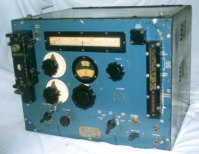 B-29 Radio Receiver |
Controls All the controls are located on the front panel. The BAND CHANGE switch selects the appropriate frequency coils and also rotates a drum, that shows a long frequency scale behind the top window. It covers four low frequency bands, which are, Band 1: 15-38 kcs, Band 2: 38-90 kcs, Band 3: 90-240 kcs, and Band 4: 240-550 kcs. The lower round window has 2 scales for logging, and these are geared to the tuning knob, which moves the scales and moves a pointer along the top scale. It has a flywheel and spins along nicely. There is an HF gain control for the RF amplifiers on the front panel and an LF gain control for the audio amplifier, behind a cover. |
The main function switch has a centre HT OFF position which is used for standby. There are 2 positions to the right and left of this. The right 2 are for R/T reception, and the left 2 are for CW which turns on the heterodyne oscillator. There is a narrow audio filter tuned to 1 kcs for CW reception, and this is switched in in the final position to the left and right. So the positions are labelled (going clockwise), FILTER IN, OSC ON FILTER OUT, HT OFF, OSC OFF FILTER OUT, FILTER IN. There is a CRASH FILTER which can be switched IN and OUT with a toggle switch to protect the audio output from large levels. There are 2 output jacks for headphones. They use a tip/ring/sleeve jack for a balanced output. Using a tip/sleeve plug will short circuit half the output transformer winding. There is a high impedance output on the right hand side terminal strip, intended for high speed reception, and is normally connected to another amplifier.
The AERIAL TRIMMER is used to tune the aerial. It has a switch on the same shaft to select the loop or uni-pole aerial. It is labelled TUNE, STANDBY (where the aerial trimmer is inactive), LOOP1 and LOOP2. There is a loop terminal block and a uni-pole aerial terminal block. The HET VERNIER control is used to vary the BFO note. Both these controls are on the left hand side of the front panel.
There is an R.I.S. control and terminal block at the top right hand side of the front panel. This is for Radar Interference Suppression, and uses an input from any radar set to silence the receiver. The input is fed through the RIS control to the screen grids of the RF valves, and will cut them off during radar pulses.
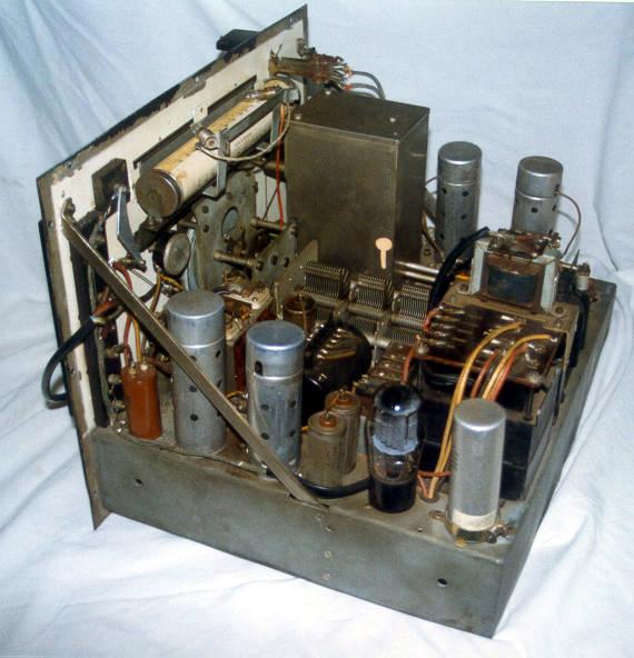 B-29 Radio Receiver Internal View |
Design The receiver follows conventional mechanical design, with a chassis and front panel, inside a metal box, with a hinged lid. Removing the front panel screws allows the receiver to be withdrawn from the cabinet. The construction uses plated and painted heavy gauge steel sheet. Like all Navy equipment, is is heavy, weighing 82 pounds. It is a T.R.F. (Tuned Radio Frequency) receiver, which is a little unusual as the other receivers in the CR series are super heterodynes. It has 2 stages of RF amplification using VR100 valves, tuned by a ganged tuning capacitor. It has a VR99 as the detector and BFO ( Beat Frequency Oscillator). It has 2 stages of AF amplification which uses an NR68 and a 6J5. It has 2 aerial inputs, for a normal aerial, and for a loop aerial. |
The loop is used on bands 1 and 2 only. A submarine can use a submerged loop on these lower bands. There is a gas discharge arrestor , behind the left hand terminal strip, to protect the input circuits from high voltages.
The BFO is called an oscillator, and performs the same function as a conventional BFO,
but in a different way. A normal BFO is at the same frequency as the IF frequency in a
super heterodyne, and is varied slightly to give an audible heterodyne.
This receiver has no IF. The BFO must therefore, be the same as the receiving frequency,
and be able to be varied slightly. An extra gang on the tuning capacitor tunes the
oscillator, and this tracks the received frequency. A front panel control is then used to
vary this to produce the heterodyne.
The handbook does not quote sensitivity, but a Test Certificate in the Radio Bygones article, reports 0.1-0.15uv for 10 dB S/N.
The power supply consists of a VU71A rectifier which is only used when connected to 240 or 110 volt mains. This receiver can also run from batteries, which are 200 volts at 22 ma and 6 volts at 2 amps. The front right hand terminal strip allows connections for the power. A link strip inside is jumpered for 240, 110, or battery power.
Restoration
The receiver was in a working condition when I purchased it. All it needed was a little
tidying up. The aerial knob operates a switch through a series of levers, and I re-keyed
one lever as the knob did not point at the correct names.
It had a white 2 core figure eight mains lead coming out of the top cover, so that the lid would not close. The terminal block on the right hand side of the front panel was where the mains should be connected, but I chose instead to use a hole in the back and run a black 3 core flex to the back of the right hand side terminal block. It looks neater, and is safer, but it can have the mains reconnected to the terminal block, and have the cord removed easily, if required. You have to make some personal decision about safety verses originality. I replaced 4 plastic wires inside with the original type of cotton covered wire. The filter capacitor and choke in the HT line had been bypassed, so I wired that back in. I don't know why it had been changed.
The paint is chipped on the blue front panel and crudely patched up, but I didn't change it, as this looks like normal wear and tear. The front panel paint is generally very good, with only a few places showing worn patches. The front panel screws do not look original. The case is painted black and looks too good to be original. The inside is painted cream, with a big paint run, visible in the interior photograph. The internal paint is discoloured where it is close to hot valves and so has been painted for a long time. I assume it is original. I have not aligned it as it seems to perform well.
References
Admiralty Pattern S.S.104 Book of Instructions for Receiver B-29, Admiralty Signals
Establishment, c/o G.P.O. London, 1941.
The Marconi CR Series of Receivers, G.L. Grisdale, Radio Bygones, Number 31,
October/November 1994, Page 17-25.
Visitors to this page since 20 February 2000
Back to Your Articles Index Page.
Army Radio Sales Co. Home Page.