|
|
I first saw this radio in a display case at the Signal Corps Museum at Fort Monmouth
back in the 1970's. Supposedly captured in Vietnam, it was a set that I had not seen as of
Sept 1968 when I left so I concluded that it must have entered service with the NVA after
1968. The set looked to be about the size of a carton of cigarettes, was displayed out of
the case and did not have any accessories. I recently picked up two of these sets. One is labelled 702D and the other had no data plate but appeared to be an earlier version of the same set. I concluded that it must have been a 702, 702A,B,or C version. I will begin with a description of the set which I believe is the older set. The set comes in an aluminium case and is 10 " long over-all, by 3 1/2 wide by 2 1/3 deep. The case has a steel D ring attached so it can be attached to a set of pack straps. The bottom of the set has two screws which must be removed, allowing the removal of the cover, which is then turned and allowed to follow the entire set as it is slid out of the case through the top. |
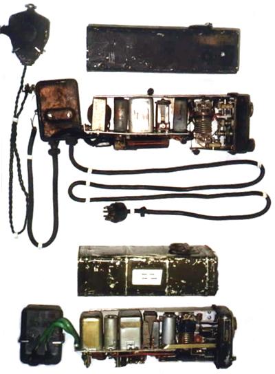
The radio is built on a heavy gauge aluminium chassis that was stamped out of a sheet of aluminium. The chassis is fastened to the top panel by 8 rivets. The top panel contains the antenna connector, a ceramic like socket to which an antenna is screwed in. There is a main tuning control which is a friction drive to the variable capacitor. The variable capacitor also has a dial with graduations which appear under a small window. There is also a push/pull switch which serves as an on/off switch.
Below the top cover is the tuned circuit, consisting of a main variable capacitor with two stator plates and three rotor plates and two more much smaller air variable capacitors. One can be adjusted only after the set is removed from the case. The other small variable capacitor can be accessed from the out side of the case by a small screw driver. It is connected to the antenna. The coil is wound on a flat piece of clear plastic with a cross brace in the form of a X and the second part of the coil is wound on a circular piece of clear plastic mounted on top of the X form. The coil is 6 turns of 16 gauge silver coloured wire with the antenna coil being 4 turns of 22 gauge wire. Above the coil is a press down switch which is accessible from the outside of the case. I assume it was for transmitting a code signal. Base on the fact that most Chinese Military sets operate between 2 to 12 MC, I conclude this set is in the same range.
|
|
Below the elements of the tuned circuit, was the radio proper. The older of the two sets has RCA 3S4 tubes. There were two of these tubes mounted in sockets with metal spring loaded shields. From right to left, there were the one tube and a large paper capacitor, then a multi pole relay, then a potted transformer, the second tube and another paper capacitor and a final un-potted transformer. Below these or what might be called the underside of the chassis were resistors, capacitors and what I assumed to be an RF choke. |

The capacitors looked like the standard 1940 mica capacitors and or moulded/paper capacitors. I counted four resistors, three of which were 1 watt size and one was a half watt size. There were five mica capacitors and one .05 MFD moulded capacitor, which was made by the Sing Kee Condenser Works. These were either soldered directly to the tube sockets or to two terminal strips. The other two capacitors which were on top of the chassis were too difficult to examine for size and manufacturing specifications.
Two rubber covered cables were wired to the circuit and fed out through the base to a power plug or the mike/headphone combination. The power cable terminated in a plug that was then plugged into a battery. The battery plug had been broken open, and three wires were then soldered to it, apparently in an effort to get power from a US battery of the required voltage.
The other cable was connected to something that was missing. What appeared to be a mike with a push to talk switch was partially soldered on (one of three wires were soldered and the others were not connected to anything) The three wires to the mike were not rubber covered and appeared to be an attempt to make a field repair. The mike that was with the set, resembled an old style. The cover was held on by three screws. Removal of the cover revealed a badly deteriorated rubber gasket. Removing what was left of it, the mike appears to be a standard carbon telephone mike. Below this were to lever switches which were controlled by the PTT switch. The switch brought the mike into a circuit and the other switch probably operated the relay, RY 1. The three wires that came in did not appear to be field modifications or were a high quality soldering job. They were also braided so it is possible they came from the factory that way.
It was my opinion that this was supposed to be both a receiver and transmitter. Pressing a
PTT switch would activate the relay and "re wire" the circuit. Most probably in
the receive mode the one tube was a detector and the other an amplifier. In the transmit
mode, one was the oscillator and the other the modulator.
Not having the accessories, a power source and with broken components, it was impossible
to do more with the set. I assume that it was adequate for short range communications. It
also had some problems and/or design flaws which were corrected in later versions.
Numerous changes occurred between the set described above and the 702 D version. The first and most obvious change was the elimination of the hard wired battery and headset/mike cables. These were replaced by sockets and the battery cable must have had two plugs, one on each end. The mike/headset also had a plug. This change made it easier to remove the set from the case to work on.
The open transformer was replaced by a potted transformer. I assume that they exhausted
their supply of old style transformers while making the first radios and by the time of
the D series, all transformers were potted.
The area of the tuned circuit has been changed. The variable capacitor in the antenna
circuit has been eliminated, as has the variable capacitor across the coil. The latter
having been replaced by a smaller adjustable capacitor rather than the air variable of the
older set. The main tuning capacitor remains the same. The tone transmitter switch has
also been removed, thus making the outer case easier to manufacture. A small light bulb
has been added to illuminate the tuning dial. Otherwise the tuning circuit remains the
same. A large coil has also been relocated from under the chassis to a position nearer the
top of the set.
The underside of the chassis has also been "streamlined" and all parts are easier to get to. There are 8 mica capacitors, still of the 1940 style but with numbers rather than a dot colour code. and 10 resistors. RY 1, the relay has been changed. The older set had two contacts and the newer one has four contacts. In the newer set, the relay appears to be adjustable and there is a screw adjustment on the top. This appears to be a factory adjustment as the screw is painted fast. This set also had tubes of Chinese manufacture.
Without having a technical manual, schematics or necessary accessories, it is not possible to do more than describe the sets and draw some general conclusions. These sets appear to have been inspired by the WW II BC 611 for size and intended purpose and the circuits inspired by the Japanese Type 94-6, only because of the use of two tubes and two transformers. This however is not a Japanese invention and the circuits or concepts were well known by the late 1930's.
The changes in the power cord and headset/mike appears to have been prompted by experience in the field. It may also reflect the fact that the cords and cables suffered damage in rough handling and that it was easier to supply new cables than to turn the set in to have the hard wired cables replaced.
This set would appear to have been developed in the late 1950s and in use during the 1960s. By the 1970s transistors were coming into use and this set was phased out in favour of some other radio. For it's time frame and intended use, the set appears to be adequate and up to the task. Operational testing may prove otherwise.
Back to Communication Equipment of The North
Vietnamese Army and the Viet Cong.
Army Radio Sales Co. Home Page.