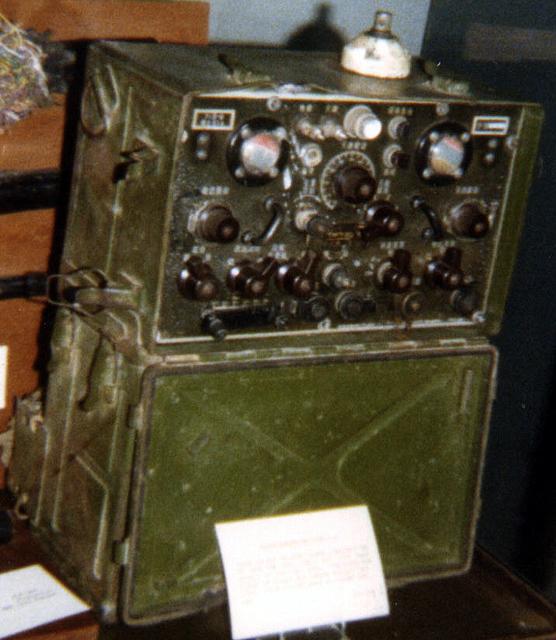
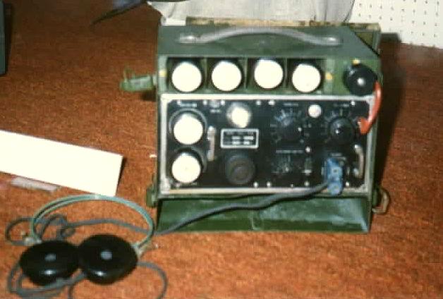
Chinese Type 71 B Radio
Transceiver
Manpack AM radio which weighed 45 lb. It covered 1.9 to 7.2 MHz and was 61/2" x
12" x 15" Power was provided by a D71 dry battery with taps for 1.5V, 7.5V, 90V
and 150V.
 Chinese Type 71 B Radio Transceiver |
|
 Chinese Type 71 B Radio Transceiver |
|
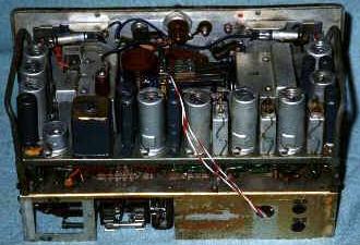 Chinese Type 71 B Radio Transceiver Internal View |
 XD 6 Radio Station |
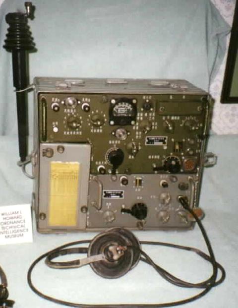
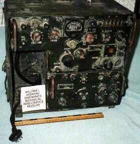
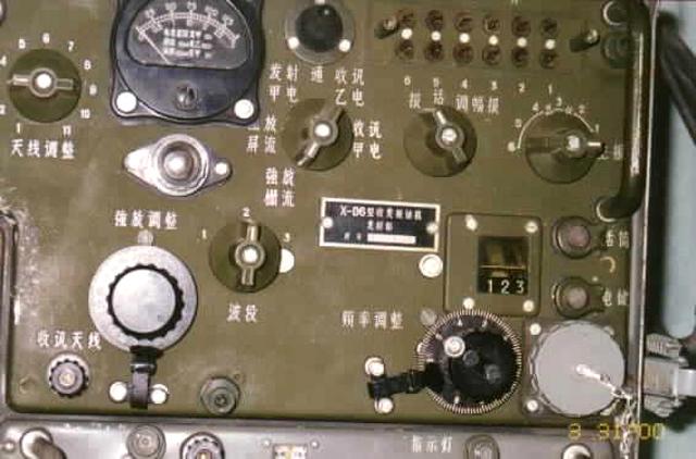
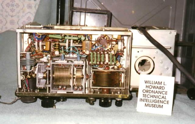
Chinese Type 102E / XD 6
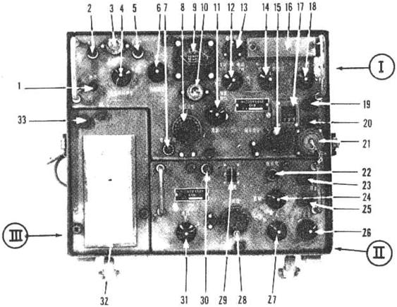
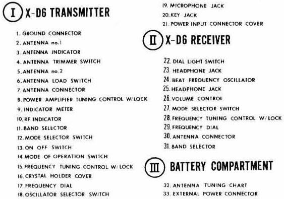
Radio Station One of the most often captured radios was the Chicom Model 102E which was man-packed or mounted in vehicles. This set was a copy of the U.S. AN/GRC 9 set with a few changes. The transmitter took up more space and the outer carrier, a metal chest housed the transmitter, receiver and a space for the D81 dry battery. The transmitter required a 6410 hand cranked generator or a 964IE Dynamotor. The hand-cranked generator looked just like the U.S. versions but had a built-in voltmeter, an idea first seen in WW II Japanese generators. The set was a 15 watt set with a range of 75 miles, and covered 2-12 MHz. The complete set with accessories weighed 105 lb. The receiver and transmitter alone weighed 38 lb. This set was being replaced by the XD 6 set which had the same technical characteristics. |
 Type 102E Radio Station |
|
 XD 6 Radio Station |
|
 XD 6 Radio Station |
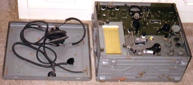 XD 6 Radio Station |
|
 XD 6 Radio Station |
|
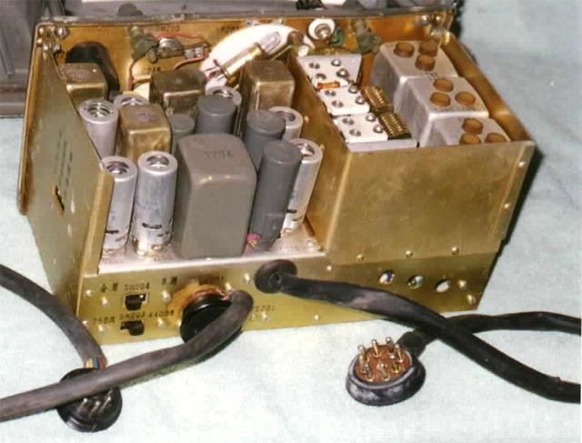
 XD 6 Radio Station |
 XD 6 Radio Station |
|
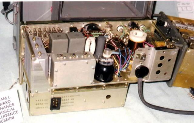
 XD 6 Radio Station |
|
 XD 6 Radio Station |
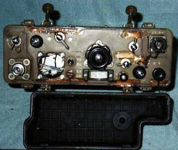
Type 139 Receiver
The Type 139 radio receiver was a manpack AM set which could be interchanged with the
receiver of the 102E set. It was contained in a thin sheet metal case with a snap-on
battery case and had a switch for connection to an external battery. The set weighed 10
lb.. without the batteries and was 61/2" x 101/2" x 11" and covered 2-12
MHz. Power requirements were I.5 V and 90V. This set was known to be used by the Viet
Cong.
Type 7512 Receiver
The Chinese type 7512 Radio Receiver was an AM table model receiver that was well
constructed but very heavy at 90 lb.. It was designed for fixed station use and operated
on 110 or 220 volts. This set covered 1.5 to 25 MHz in 8 bands. Needless to say this set
required access to commercial power or a portable generator.
 Type 63 Back Pack Radio |
Type 63 Back Pack Radio The Type 63 manpack set was the newest item supplied by China. This set was probably intended as a replacement for the Model 71 B radio. This set looked like a copy of the U.S. W.W.II Walkie-talkie but when the RT unit was removed from its case, it looked more like an AN/PRC 10. It weighed 35 lb.., was 3 1/2" x 10" x 16" and was powered by a D-63 dry battery with taps at 3V, 27V, 90V and 178.5 volts. It was estimated to be a 2 watt transmitter and covered 1.5 to 6 MHz. Unlike the U.S. counterparts this set had a built-in key for CW operation. |
 Type 63 Back Pack Radio |
|
The Type 601 C Transmitter
The other major Chinese set that had been captured by Allied Forces was the Chinese Type
601C Radio Transmitter. This was a high power set that was table or vehicular mounted. It
weighed 45 lb.. and was 20" long, 8'. high and 8 1/2" deep. The power
requirement was 6 volts and 500 volts from a generator or Dynamotor. This set was
estimated to have a range of 75 to 2000 miles, again in the 2-12 MHz range with 3 bands
and 6 pre-set crystals. Again, it was capable of voice or CW. This set was probably
intended for communication between a major headquarters and Hanoi.
In addition to Chinese manufactured radios, there were Soviet generators. large Polish storage batteries and a host of small transistor AM sets from all over. In mid-1968 we recaptured an AN/GRC 9. a set from the 1950's that had been supplied to the South Vietnamese as part of the MAP - Military Assistance Program. It was captured by the VC and put into service on their side.
Soviet assistance in the area of radios was minimal. In late 1967, the 1st Cavalry Division Air mobile captured a Soviet R607 naval radio. It was captured while being landed from the sea. It never actually saw service in Vietnam. This was a huge set-up, designed for installation on a ship or for a fixed base station.
 VTS-2 Radio |
The VTS 2 Receiver The only known set of North Vietnamese manufacture was the VTS-2 Radio Receiver. It was contained in a square metal box. The set was 10" x 8" x 7" and used plug-in, tube shaped coils. There were six coils, four were stored in the top of the receiver, and two were in use. It used ten D cells for power and covered 1.9 to 12.2 MHz. The use of D cells made it very easy to purchase replacements on the local economy, a prime consideration for an army whose supply lines, better known as the Ho Chi Minh Trail, went through miles of jungle and was subject to constant bombing. In addition to these sets, the Viet Cong used a number of "home-made" sets. The set described in the 1967 T.l.B. was a CW receiver and transmitter housed in a 50 cal. ammo can, 6" x 8" x 11" and weighed 11 lb. without the battery. |
It was a 2 watt set with a range of 2O miles covering 3.8 to 6.8 MHz. It required I 1/2 volts for tube filaments and 90 volts and 150 volts for plate supply. It had a hand wound coil. (In a previous article I described the reconstruction of a VC home-made radio in a 30 cal. ammo can. This 30 cal ammo can set was not covered in the 1967 T.I.B. so I assume it was captured much later in the conflict.) The article is included here, on the following pages.
The technical intelligence bulletin was never updated or reissued during the course of U.S. involvement in Vietnam. By 1972 the CMEC was shut down and the units were returned to the United States. In 1975 D Co./519th Military Intelligence Battalion was transferred to Aberdeen Proving Ground and began to function as a technical intelligence unit. A new and updated Technical Intelligence Bulletin was issued in the late 1970's. Included in the new T.I.B. was the Mercury Talk Transceiver, examples of which were on display at the Signal Corps museum and at Aberdeen Proving Ground. It is assumed that examples of this set were recovered in Vietnam in the latter stages of the conflict.
More Information on the North Vietnamese VTS-2 Receiver
The only known set of North Vietnamese manufacture was the VTS-2 Radio Receiver.
The "VTS" designation stands for a North Vietnamese war heroine, .Vo Thi Sou,
apparently a heroine, although the only evidence that can be found on her is
that internet search engines turn up a list of airline offices in Saigon, one of
which is on a street named Vo Thi Sou.
The set was contained in a square metal box. The set was 10" x 8" x 7" and used plug-in, tube shaped coils. There were six coils, four were stored in the top of the receiver, and two were in use. It used ten D Cells for power. The use of D cells made it easy to find replacements on the local economy, a prime consideration for an army whose supply lines, better known as the Ho Chi Minh Trail, went through miles of jungle and was subject to constant bombing. In addition to these sets, the Viet Cong used a number of "home-made" sets. The set was first described in the 1967 T.I.B. While I was in Vietnam, from fall 1967 until August 1968, I never saw one of the VTS-2 sets. The first time I saw one was behind glass at the Fort Monmouth Museum in the 1980s.
In the fall of 2000, I was contacted by Dennis Hoffman of Wisconsin who had just gotten one of these sets. After several e-mail discussions, he was kind enough to loan it to me for study and display. It arrived in June 2001.
Physical Layout
The set is well constructed and the outer case is made of heavy gauge sheet
metal. The case is 7 inches deep, 10 1/2 inches wide and 8 1/2 inches high The
front cover is held on by four spring loaded clamps. Removal of the front cover
reveals detailed workmanship in it?s manufacture. It even has a rubber gasket to
make it water proof. The front section has three compartments. The top section
which is 1 3/4 inches, houses the four coils not in use and the power connector.
The centre section houses the radio itself and the lower compartment, also 1 3/4
inches holds the headset, antenna wire and any other accessories or spare parts
that may be issued with the set.
The front compartments are 4 1/2 inches deep. The rear compartment which is 1 1/2 inches deep houses the batteries needed to run the set. The rear cover is held closed by two captive screws and is hinged. Several panels of spring loaded contacts hold the batteries. It appeared that there were originally cardboard tubes to hold the batteries. These have long since deteriorated. The battery terminal boards are wired together and are fed through a junction block to the power socket on the front. The power socket is a local tube base and the plug in coils also use octal sockets. Power supplied to the set is 1.5 volts, 6 volts and 6 volts for a total of 12 volts.
Circuit Design and Controls
The radio set itself is a bit more complex than it has to be. It is actually two
modules. These are made of light gauge metal. and are bolted to the front panel
by four screws for each module. The set is unique in that it is a two tube
regenerative receiver with a four transistor amplification stage. Facing the
set, on the far left are two holes for the plug in coils. On the bottom left is
a screw binding post which is for the ground connection. On top is a socket for
a plug in item which was the antenna connection. It was labelled ANG TEN. This
module is mounted to the front panel by stand off spacers. This allows the
tuning capacitor drive unit to be mounted between the front panel and the front
of the module. The tuning dial is graduated from 0 to 180. An outer knob is a
speed dial and the inner is for fine tuning.. The dial face is visible through a
magnified lens which can be illuminated. Tuning is done by a two gang variable
capacitor. The two plug in coil sockets are housed in a metal box which provides
some shielding.. At the rear of the module are two 7 pin tube sockets and the
1T4 tube seems to be the RF amplifier, and the 1 R 5 tube is the detector stage.
The 1T4 socket is mounted to the metal chassis and the 1R 5 tube socket is
mounted on rubber spacers.
The second module is the amplification section and is a bakelite board mounted on the metal chassis. This bakelite board is where the components are mounted. It resembles the late 1940s type circuit in the days before printed circuits were used. Across the top are two potentiometers marked 1 - 10 and labeled PHAN UNG and AM LUONG. Across he bottom are another dial for a small variable capacitor, labelled DIEU CHINH CAO TAN, a slide switch labelled MO and TAT (On -Off). and to the far right are two sockets for the headset (s). One is for 4,000 ohm headsets and the other is for 250 ohm headsets. There is also a push button which lights the dial lamp. The set came with a 4000 ohm headset. An interesting feature of this headset is the plug which will allow another headset to be plugged in to the first plug so two people can listen.
It can be seen from the schematic, this is a most unusual set. The RF stage and the detector stage are tubes while the audio amplification is transistorized. Even more unusual is the fact that the tubes, which one normally thinks of having plate voltages from 22 1/2 to 67 volts are being operated with only 12 volts.
The circuit is a regenerative grid leak circuit feeding the plate output to transformer Tr 1. Regeneration is controlled by potentiometer Po 1 The out put from Transformer Tr 1 is then sent to the transistorized amplification module and , while I am not well versed on transistor circuits, I think the first two steps are referred to as cascade steps and then to transformer Tr 2 and then to a Push Pull amplifier with it?s output to transformer Tr 3. Transformer Tr 3 ?s secondary is wired to the head set plugs, the full secondary to the 4,000 head set connection and the centre tap to the 250 ohm headset socket.
According to the book "Basic Communications Electronics" by Hudson and Luecke, "If more gain is required, transistor amplifiers may be connected together (cascaded) to provide more gain than is available from one stage alone. Most systems needing amplification will have multiple stages of gain and even have different types of amplifiers, including emitter--followers... Amplifiers of this type can have voltage gains well into the thousands. Where designing cascaded amplifiers, the designer must check the last stage in the chain to make sure it is not over-driven, which would cause distortion. The push-pull amplifier uses transformer coupling at both its input and its output. This type of amplifier will have a voltage gain greater than 1 and also exhibit current gain. As with the complementary-symmetry amplifier, each transistor operates for only one-half of the input signal cycle. When the input signal is positive, transformer action produces a positive voltage on the base of Q3 and causes it to conduct. The changing current in the collector is transferred through the output transformer to the load . A negative input signal causes Q4 to conduct and its changing current in the output transformer produces an output voltage across R4. The bias provided from +V through R5 and R6 to the bases of Q3 and Q4 is such that Q3 and Q4 are just at the verge of conduction with no signal. This amplifier uses two of the same type transistors and only a positive voltage power supply."
Operating The Set
The operators manual is dated on the front page by the operator as 25 November
1964. It starts off with /General Introduction ( Gioi Thieu Chung), then Part II
is Components of the Machine (Cac Bo Phan Cua May). Part III Design and Theory
of Operation, Part IV Maintenance and Repair, and components charts and coil
data.
The set covers the frequency range from 2 MC to 12 MC using three different sets of coils. First one must install 10 D-Cell batteries in the rear compartment. Then open the front cover and check to make certain that you have the correct set of coils for the frequency you wish to receive. A 1 and B 1 covers, 2 to 3.7 MC, A 2 and B 2 cover 3.5 to 7 MC and A 3 and B 3 coils cover 7 to 12 MC. Plug in the headphones, turn the set on and tune to the correct dial setting, based on the chart inside the front cover.
According to the operators manual, the set consisted of:
1 receiver, inside a metal box with two covers, coils (coils A1, B1, A2, B2, A3,
B3),
1 headset, 4000 ohms,1 antenna, 15 meters in length, ground cable 5 meters in
length and rod, canvas cover, bag of accessories, instruction booklet,
maintenance log. The operators manual goes on to describe the features of the
set. Features: The VTS receiver is designed for rapid tactical deployment and
use on the shortwave bands. Amplification: a 1T4T vacuum tube serves as a
low-noise amplifier, consuming low power particularly at low audio levels-
Active filtering: a 1R5T vacuum tube serves to as a filter and amplifier.
Audio frequency amplification: type 0C71 semiconductors amplify signals and feed to the push-pull type 0C72 semiconductors to provide power sufficient to drive a headset. A special feature of this receiver is its ability to be used as a jamming device for other frequencies, even while serving as a receiver.
Again, from the operators manual, Rear of unit: Open the back cover and you will see the battery compartment. The left compartment is for 1.5-volt A-batteries which are connected in parallel to provide filament power to the 1T4T and 1R5T tubes. The right compartment is for 12 volts which is the anode voltage for the two tubes. The 12-volt array is centre-tapped at 6 volts which is used to power the semiconductors. The upper 4 batteries are designated batteries B2, the lower batteries B1. The estimated battery life was as follows:2 A batteries, about 200 hours 4 B1 batteries, about 400 hours and 4 B2 batteries, about 600 hours.
Construction of the Set
Construction of this set shows a high degree of manufacturing skill. The front
panel as well as the front cover had to have been made using a punch press. The
screws used to hold components in place all have red paint applied to show they
had not been disturbed or to help hold them in place. This was a common practice
with WW II German radio sets and to some extent Russian sets. Construction of
the outer case requires the use of a break to bend the metal, however the two
modules reveal that they are a lot more complex than they have to be. Rather
than make the item from one sheet of metal, many small panels were used. I
reached the conclusion that they were stamped out on a hydraulic press but one
that could only handle reasonably small size parts, no bigger than 5 inches by 5
inches.
Cost of Manufacturing This Set
I took the list of parts and went price shopping in the Year 2000 Antique
Electronics Catalogue. I also listed the major manufacturing processes needed to
make the outer case and chassis and estimated the costs. This information is
listed in Appendix A. The estimated cost of making a single set in 2001 was $
365.42 for parts and assuming a labour cost of $35.00 per hour for a technician,
and assuming that the set could be assembled and wired in 4 hours, the labour
cost was $ 140 .00 for a total cost of $505.42.
Of course the price of the parts in 1960 was much less and the North Vietnamese assembly workers did not get paid $ 35.00 per hour. I would guess that parts cost would be about half.
The U.S. Army Area Handbook for Vietnam , September 1962, reported the following: "The Ministry of Labour and the Ministry of Light Industry set wages in fields according to the nature of the work performed. Salaries and family allowances, previously combined, were separated in 1959. The new law "According to government sources, the average monthly industry wage increased from the equivalent of 39 dong a month in 1955 to 66 dong in 1960.A Western observer estimates the monthly earnings in 1961 as follows: unskilled workers, 40 dong: skilled workers, 40 to 60 dong; the most highly skilled miners, 150 dong; factory managers, 100 dong; government ministers, 200 dong; and engineers, 250 dong." Incidentally, a dong in 1959 was valued at $0.263 US. Considering radio assembly workers as skilled, this works out to about 71 cents per day !
Summary and Conclusions
This radio set represents an effort by North Vietnam to enter the
electronics field and possibly develop a capability independent of China and the
U.S.S.R for completed units, however the components all came from either the
Warsaw pact or China. As it is easier to send vast quantities of parts in less
space than completed sets, it may have been an effort to cut down on
transportation costs and the risks involved. It also reflects a desire for a
reliable set that did not depend on hard to obtain and supply dry cell batteries
or complex power supplies.
It also makes use of both tubes and transistors but is not really a transition set as they manufactured nothing before except some very crude "home brew" sets and little afterward. According to my electrical engineer friend in China, the components were made in China. The variable capacitors usually used in old tube radios were made in Shanghai China, the white ceramic tube capacitors were made in Tianjin China, double circuit is its trade mark, they are very old, and not produced in China anymore. He thought the transistors were also made in China. 3AX**(Ge-PNP-AF). However , my HAM radio contact in Russia said: "Electrolytic capacitors are from Czechoslovakia, TESLA electronics plant. Some thick green resistors look like of old Russian VS type. Other smaller green and pink ones look like WWII German and post-war Russian duplicates. Trimmer capacitors and mica caps look like Russian or, possibly, also Czech ones."
The operation of the tubes with only 12 volts plate voltage shows a remarkable and innovative use of the tubes. The data plate on this set had 64 - 0293 or 5. I assume that 64 means it was made in 1964 and was set serial number 0293 which means that there were not very many of these sets made and fewer still captured by US Forces, compared to the usual Chinese supplied radios, the 102E, XD 6 and Type 63 sets.
This set?s value comes from the fact that it is a rare set, was not made in quantity, and was a part of the Vietnam War. There are, however very few Chinese radio sets and even fewer collectors of Chinese radio sets. I would place the value of the set at $500.00 U.S. dollars and that figure based on the cost to replicate it.
Manufacturing Costs
Part AES # each total
RF SECTION
Antenna connector S-HF2-930 $4.50 $ 4.50
2 gang capacitor (15-140 Pf) C-V300-145 $9.95 $ 9.95
variable capacitor (5-50 Pf ) C-V100P $17.95 $17.95
6 coil forms PC-211 $4.95 x 6 = $29.79
2 coil sockets( 5 pin for above) PST8-484 $3.80 $ 7.60
2 7 pin tube sockets PST7-311(C) $3.95 x 2 = $ 7.90
2 Tube shields PSS7-160(C) $1.50 x 2 = $ 3.00
Potentiometer $ 1.75 $ 1.75
1T4 tube $3.05 $ 3.05
1R5 Tube $5.70 $ 5.70
7 Resistors @ 5 for $1.60 $ 2.24
2 RFC Choke (50 Mh and 30 Mh required) $3.88 x 2 = $ 7.76
6 capacitors @ $0.63 each $ 3.78
AUDIO AMPLIFICATION STAGE
2 Interstage transformers P-T20D89 $13.95 x 2 = $ 27.90
1 output transformer P-T156 $14.95 $ 14.95
4 transistors $ 2.00 x 4 = $ 8.00
Potentiometer $1.75 $ 1.75
slide switch P-H35-242 $1.50 $ 1.50
4 pole headphone socket
POWER SUPPLY SECTION
2 cell C-Cell holders (5 needed) $0.75 x 5 = $ 3.75
8 pin loctal socket PST80185 $2.50 $ 2.50
8 pin loctal plug $ 3.00
CASE Job shop estimated cost, single unit, 1960 price
Outer case with canter panel $75.00
rear cover with hinge and screws $25.00
4 spring clamps @ $5.00 each $20.00
coil holder form $10.00
Front cover $25.00
Radio and radio modules
Front panel $10.00
Chassis modules 2 needed @ $10.00 each $20.00
Bakelite panel $ 5.00
Dial marking kit SM 175 $ 3.95
Magnifying lens $ 5.00
Verneer type drive No longer manufactured $20.00 when found in flea markets
2 knobs PK 198 $4.50 $ 9.00
Misc. screws and nuts $ 8.00
Headset PA 466 $15.25
Total, parts $365.42
CASE Job shop estimated cost, single unit, 2001 price (Dunrite Metal Co.)
Outer case with centre panel $
rear cover with hinge and screws $
4 spring clamps @ $5.00 each $
coil holder form $
Front cover $
Radio and radio modules
Front panel $
Chassis modules 2 needed $$1,500.00
Bakelite panel $ 5.00
Dial marking kit SM 175 $ 3.95
Magnifying lens $ 5.00
Verneer type drive No longer manufactured $20.00 when found in flea markets
2 knobs PK 198 $4.50 $ 9.00
Misc. screws and nuts $ 8.00
Headset PA 466 $15.25
Total, parts $1865.42
Translation of the Operators Manual V. T. S. Receiver
General Introduction
The VTS Radio Receiver (the designation honoring heroine Vo Thi Sau) is an
electronic product of our manufacture. It was produced at the request of the
battle units.
The VTS Receiver can be used with either AC or battery power. It features high sensitivity, power conservation and compact size. It can be used widely in the field from battalion to unit level.
Technical Characteristics
(1) Uses: The VTS Receiver operates on shortwave bands, it's easy to carry and
assemble quickly. It can be used to transmit and to receive.
(2). Frequency bands: Coverage from 1.9 to 12.2 MHz, divided into 3 bands:
Band 1 - 1.9 to 3.9 MHz
Band 2 - 3.7 to 7.2 MHz
Band 3 - 7.0 to 12.2 MHz
The surface of the receiver is divided into sections to correspond with the frequency of the three bands (see the frequency diagram on the cover.)
(3) Sensitivity: Power to headset - 100 mw with 25> on all three bands
Sensitivity on all 3 bands:
Transmitting 5 uv +/- 2 uv
Receiving 50 uv +/- 20 uv
(4) Selectivity: At -10 dB:
Transmitting +/- 6 KHz
Receiving +/- 60 KHz
(5) Power: 1.5V, 6V, 12V DC; consumption 200 mw
(6) Dimensions: 280 x 220 x 180 mm
(7) Weight: 7.2 Kg (including batteries, receiver, antenna, ground cable and
rod)
Components
1. The radio set consists of:
1 receiver, inside a metal box with two covers
6 coils (coils A1, B1, A2, B2, A3, B3)
1 headset, 4000 ohms
1 antenna, 15 meters in length
1 ground cable 5 meters in length and rod
1 canvas cover
1 bag of accessories
1 instruction booklet
1 maintenance log
Front Panel and Functional Knobs
- Spare coil (there are four coil sockets to hold the spare coils)
- Battery compartment: the top right compartment is the power connection
- Coil compartments A, B: used for operating coils, for the desired band
- Antenna compartment; terminals for ground cable and antenna cable
- Tuning; divided into 100 increments to set frequency
- Concentric tuning knobs: large knob is course tuning, small knob is
fine-tuning
- Regeneration adjustment
- On/Off switch: turns power on (up) or off (down)
- Volume control: adjusts audio level to operator's preference
- Headset jack: one jack for 250 ohm headset, one for 4000 ohm headset -- use
care to match headset impedance to the correct jack
- Headset compartment: to stow headset when not in use
Rear of Unit
Open the back cover and you will see the battery compartment. The left
compartment is for 1.5-volt A-batteries which are connected in parallel to
provide filament power to the 1T4T and 1R5T tubes. The right compartment is for
12 volts which is the anode voltage for the two tubes. The 12-volt array is
centre-tapped at 6 volts which is used to power the semiconductors. The upper 4
batteries are designated batteries B2, the lower batteries B1.
Features
- The VTS receiver is designed for rapid tactical deployment and use on the
shortwave bands.
- Amplification: a 1T4T vacuum tube serves as a low-noise amplifier, consuming
low power particularly at low audio levels
- Active filtering: a 1R5T vacuum tube serves to as a filter and amplifier.
- Audio frequency amplification: type 0C71 semiconductors amplify signals and
feed to the push-pull type 0C72 semiconductors to provide power sufficient to
drive a headset
- A special feature of this receiver is its ability to be used as a jamming
device for other frequencies, even while serving as a receiver.
Operating Detailed assembly
After placing the receiver in a suitable location, open the cover and put
the cover aside. Remove the accessories such as headset, antenna, ground cable,
ground rod and prepare for operation.
1. Erect the antenna in a clear area, about 5 meters high and connect to the
antenna socket.
2. Put the ground rod on soft soil, connect the ground cable to the ground cable
socket. In strong signal conditions, the ground connection may not be necessary
but the sensitivity of the receiver will be reduced.
3. Connect the headset to the headset socket, observing correct impedance
4. Make certain that the coils (A, B) match with the frequency and socket (A
above, B below) - they are not interchangeable.
- Band 1 1.9 - 3.9 MHz; use coils Frequency A1, Regeneration B1
- Band 2 3.7 - 7.2 MHz, use coils Frequency A2, Regeneration B2
- Band 3 7.0 - 12.2 MHz, use coils Frequency A3, Regeneration B3
5. Find the desired frequency on the chart on the cover and use that figure
to set the tuning dial. For example, 5400 KHz matches 55, 8300 KHz matches 75.
6. Turn the tuning knob to the correct number. Turn the volume control near
mid-range, set the regeneration control to 0.
7. Turn on the power. If you hear noise, it means that the unit is functioning
8. Adjust the regeneration control until you hear a rushing noise. If
transmitting, continue to turn the knob until you hear the strongest noise. Tune
the smaller frequency control knob to locate the desired station. If receiving,
reduce the regeneration control until the rushing noise disappears, then
fine-tune the frequency.
9. Repeatedly fine-tune the frequency and readjust the regeneration control
in small increments until the signal sounds proper.
10. Increase the volume to the desired level. When finished operating, turn off
the power.
Cautions to be Observed While Operating
- When inserting the coils, make certain that the coils match the desired
frequency
- See that the A coil is plugged into the A socket and the B coil is in the B
socket (see tuning chart)
- Observe polarity when inserting batteries: the large contact (negative) should
touch the spring-coil contact. Make certain that the spring-coils are compressed
so that the batteries make proper contact. All B batteries must have the plastic
cover in place to maintain integrity.
Design and Theory of Operation
The VTS receiver utilizes hybrid technology, combining both vacuum tubes and
semiconductors. High-frequency stages use vacuum tubes; low-frequency stages use
solid state.
High Frequency
The 1T4T tube has three control grids energized by low-power filament and
serving with a low-voltage anode. Components coils L1 & L2 and capacitors C1, C
and CV1 select the desired signals from the antenna, with components L2, C, C1
and CV1 forming a tuned circuit, tracking with CV2 below. The amplified
high-frequency signal, in the form of varying anode current, is passed through
coil L3, coupling into coil L4. Capacitor C2 serves as a bypass to ground.
Active filtering
The 1R5T tube has three control grids energized by low-power filament and
serving with a low-voltage anode. Components L4, C3 and CV2 are connected to the
control grid, serving as a tuned circuit with CV2 ganged with CV1 above.
Components C4 and R1 with the 1R5T serve to feed the active filtering.
High-frequency signals from the above-mentioned stage are coupled and tuned
through coil L4 with capacitor C4 passing the high-frequency signals to the
control grid. The signal is amplified, through coil L5, coupling loosely back to
the input coil, providing positive feedback to increase the sensitivity of the
receiver while audio is passed to component TR1. When serving as a receiver, it
is necessary to control the amount of feedback (regeneration) to limit the
regenerative noise. In the case of transmission, additional regeneration is
applied to achieve a larger signal. The amount of regeneration depends on
potentiometer PO1 and the anode current. Components C5, C6 and C7 function as
high-frequency bypass.
Audio Frequency
The amplification stage of the VTS receiver utilizes two semiconductors 0C71 and
two semiconductors 0C72. Since the devices have the same function we will
analyze only the first set.
First, semiconductor 0C71 depends on its ability to pass current in one direction only with an input element influencing the amount of current flow; a small current flows from Emitter to Collector (anode) in this PNP semiconductor. The Base element is biased by R3 of circuit R3, R4. The semiconductor's functioning also depends to signal current connected to the base, there we connect potentiometer PO2 to control the gain of the receiver. R6, C10 connect to the emitter for bias/bypass. Semiconductor T1 is used for matching. Components C8, C11 serve as coupling to the Base elements. Input impedances must be properly matched for the semiconductors to achieve the necessary gain for the receiver, therefore TR1 is utilized for impedance matching.
The power amplification stage consists of a push/pull circuit using two 0C72 devices which have the same operation as the devices discussed above. The only difference is that the devices are configured to operate in a different class. This circuit is similar to a push/pull vacuum tube circuit. As current in one element is increased, it is reduced in the other. Resistors R11 and R12 are used for biasing of the two semiconductors, T3 and T4, which are working at class AB1. The resistors establish the proper operating point for the semiconductors. If R11 is opened, for instance, it will cause high current and destroy the semiconductor.
Power
The VTS receiver uses direct current, batteries. There are three voltage levels
supplied, 1.5 V, 6 V and 12 V.
1.5 volt supply is used for filament heat of the vacuum tubes. 6 volt supply provides power for the semiconductors. 12 volt supply provides anode power for the vacuum tubes.
Estimated Battery Life
2 A batteries, about 200 hours
4 B1 batteries, about 400 hours
4 B2 batteries, about 600 hours
Maintenance
The VTS receiver requires very diligent maintenance.
These are points you need to observe when operating the device.
1. Do not bang or drop the unit, do not place heavy weights on the equipment or
sit on it.
2. Whenever the unit is relocated, make certain to turn it off and to cover the
unit.
3. Only authorized expert personnel are permitted to disassemble, adjust or
repair the unit.
4. Use care when handling the unit, do not let it get wet or dusty. Always keep
the unit clean, dusting it with a soft cloth (note: do not scratch the surface.)
5. Screws and nuts should be securely in position, do not let them become
loose.
6. When operating, do not turn the knobs roughly.
7. When the unit is not to be used for a long period of time, or when moving a
long distance, remove the batteries. No not permit old or leaking batteries
inside the set.
8. Do not operate the unit in the hot sun, over 40-deg C.
9. Do not run it continuously for more than 4 hours. If it is necessary to
operate the unit for a longer period of time, let it rest for 15 to 20 minutes
after the first 2 hours (to stabilize the batteries.)
10. If the unit is to be run from AC electrical power, an electrician must
perform the connection. (An electrical expert must perform this.)
Repair
1. Sound is not clear, there are popping sounds. Batteries are old. Change
batteries B2, move batteries from B2 to B1 (because battery B2 has greater life
expectancy.) If it still doesn't perform properly, change to new batteries.
2. The Regeneration knob is turned to 10 and the unit still doesn't work. The batteries are dead; change A and B1 batteries, and, if necessary, also change the B2 batteries.
3. Unit is intermittent. Some component is loose. Re-seat the coils, check
the antenna and ground connections and electrical connections.
4. Unit operates but without sufficient power. Check the high-frequency and
regeneration coils to see that they match.
5. Unit functions but audio is not strong or clear. Headset is plugged in the
wrong jack, 4000 ohm headset plugged into the 250 ohm jack or vice versa.
6. Unit seems noisy. Reduce volume and/or adjust the Regeneration control. If you tap the receiver and hear a noise in the headset, change the 1R5T vacuum tube for a new one.
These are the minor problems you can fix right away. In case of major problems, you need proper equipment and an expert to perform the repair. The unit must be taken back to the manufacturer/shop for repair.
Emergency Repairs
1. The voltages measure lower than rated. Change the batteries.
2. When signals are sometimes clear and sometimes not, or new batteries are in
place and signals are still not good, check all connections. If the problem
still exists, have the unit repaired or replaced.
3. If there is no audio output but there is a sound when the power switch is
turned off to on, check capacitors C7, C9, C13.
4. Batteries are OK, but the unit has insufficient audio output volume. Check
capacitors C8, C11, C10, C12.
5. Volume control knob causes a scratching noise. The P02 potentiometer is
wearing out, remove it and clean it or replace it. If signals pop from on to
off, check (and clean or replace) potentiometer P01.
6. The two semiconductors in the back are hot (warm): check resistor R11 to see if it is open.
Voltage Chart
| Tube Type | Filament Volts | Control Grid Volts | Anode Volts | Anode Current |
| 1T4T | 1.35 | 10.5 | 0.7 | |
| 1R5T | 1.35 -1.2 | -4.8 9.5 | 11.0 | 0.03 + 0.3 |
Translated by Thuy T. Brewer, 735 N. Albemarle St., Arlington, VA 22203-1424, (accuracy not guaranteed!)
Back to Communication Equipment of The North
Vietnamese Army and the Viet Cong.
Army Radio Sales Co. Home Page.