This set was obtained at the Great Western Militaria show in November 1998.
The Markings on the data plate contain the numbers 8 1.
It is thought to be the Type 81C based on the description in Jane's it is 1.6-12 MHz in 3
bands,1.6 - 3, 3 - 6, and 6 - 12.
Dimensions: H280mm X W390mm X D115mm. Weight: 12kg Power supply: 25VDC
Power output: AM =4.5W CW = 15W (3-10W low power)
|
General Description of the set As received, the set is contained in a metal case with the transmitter in the top section and the receiver in the bottom. Overall dimensions of the case are: 4 1/2 inches deep, 10 inches wide and 11 inches high. Measuring to the top of the antenna terminal, the set is 13 inches tall. With a battery box the set would be even taller. A battery box of some form must also come with the set. This set came without it, unfortunately. Power connections are two large male pins on the bottom. There are hooks for the battery box to be attached on the bottom. There is also a socket on the side for a power connector. The set came without the power cord as that is part of the generator. |
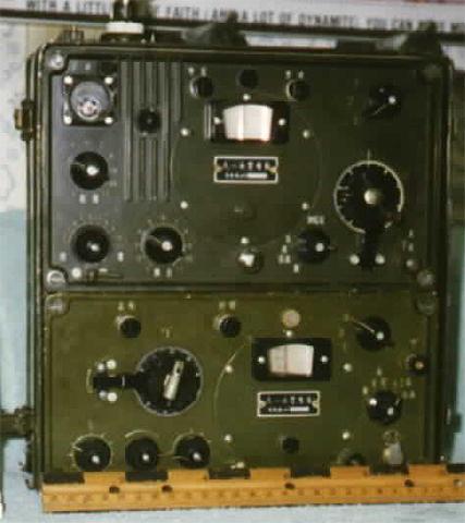
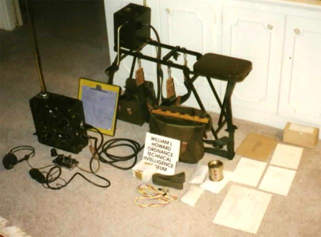 Chinese Radio Set Model 81C Transmitter and Receiver, Complete Station |
Other connections on the side are for a headset/microphone with push to
talk switch and a socket for the CW key. The receiver also has a socket located on the
front panel, for a plug in pair of headphones, which were supplied and most likely were
for the second operator who was cranking the generator. On the top of the case was the
antenna connector and three screw terminals with antenna and ground symbols. The Antenna
were marked 1 and 2 and No 2 had a metal link to the ground terminal. The set came with a sectional antenna consisting of a flexible connector, 9 inches tall, three metal shafts, each 16 inches long, and a mid section loading coil with taps, 6 inches long with electrical taps. The physical height then is 63 inches and the electrical length depends on the location of the tap connector. |
At the very top is a collapsible five pointed star radial. The set came with a very heavy silver metal key which had a standard US type 1/4 inch plug. It was in a box marked D 117 so I assume that is the nomenclature of the key. It was mounted on a very heavy base and the actual arm was very flimsy, for a tactical military radio. It would do well in a fixed base station but not for a tactical radio.
Transmitter and Receiver Units
Spring loaded snap catches (4) hold the front panel cover on the set. An additional; four
snap catches hold the battery box on the bottom. The battery box is free and can be
completely separated from the radio. The case has provisions for pack straps so it can be
transported by one man.
The Chinese Type 81 C Radio Transmitter is of late Vietnam war, if in fact it was part of
the conflict. It is probably the replacement for the Type 102E or XD 6 Radio sets which
were tube sets and was powered by a hand cranked generator and a D 81 dry cell, providing
90 volts and 1.5 volts. As of September 1968, none of the Type 81 sets or the Type 139A
sets had entered the Vietnam conflict. The set had serial number 700127 and the receiver
had serial No. 700267 . The generator had a data plate indicating it was made in February
1972. A packing list in the Generator shipping crate was dated 1971. This would tend to
confirm that the radio entered service in 1970.
|
Transmitter section Front panel Chinese Radio Set Model 81C |
Physical Description of the Transmitter The transmitter is 10 inches wide, 5 3/8 inches tall and 3 and 1/2 inches deep.
Front
Panel Controls |
Coming across the bottom is a dial, marked 1 through 11 connected to another rotary switch. Then the pull knob for removing the set from the case and then what appears to be a function switch, tune, calibrate, AM, CW off, etc. The main tuning control and clamp down are in the lower right corner, as is an antenna connector which connects the antenna to the receiver. In the top right corner is a rotary switch, marked 1,2,3 which is the band switch. The centre of the set is the frequency scale with an illuminated dial window. Above this are two small rotary switches which are for the dial light. Between the main tuning dial and the ma meter is a heat sink with a transistor sticking out with a rubber cover over it. (See photograph)
|
|
Interior construction The major feature is a shelf like frame with various printed circuit boards mounted on it. There are two exposed rotary switches which are mechanically connected to the band switch control. On the right side are clamp like connectors which slide into the antenna posts on the outer case. There is also a small relay, which I assume to be a keying relay. In the centre of the right side is the tank circuit coil and below it is the antenna trimmer capacitor. |
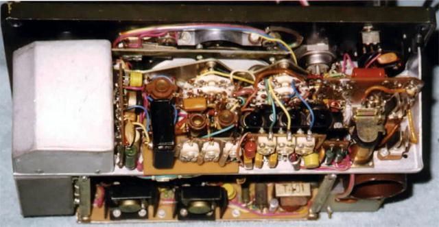
Across the bottom is another P.C. board with the most prominent features being three transistors in heat sinks. Above this is the main tuning capacitor, a three gang variable. One the far left, there is a sealed (covered ) container with the cover held in place by four small screws. Removing the cover one finds three coils wound on ceramic forms. Above these three coils is the third band switch rotary control and a small printed circuit. (See photographs)
Operating Characteristics
The tuning dial was graduated in three scales, one from 1.5 to 3.6, the second from 3.6 to
8.5 and the third from 8.5 to 18.0. I assume these are megacycles. Most of the older
Chinese tactical sets operated on 2 to 12 Megacycles. Other than the information in Janes,
no further information is available. As I did not have a battery box or schematic, I did
not make any effort to test the transmitter.
The Chinese Type 81 C Radio Receiver, like the Type 139 A is also late Vietnam war, if in fact it was part of the conflict. It is probably the replacement for the Type 139 Radio Receiver which was a tube set and was powered by a 90 volt dry cell and 1.5 volt dry cells. It is the same receiver as is found in the Type 139A Receiver. As of September 1968, none of the Type 81 Radios nor the R 139A sets had been captured by US forces to the best of my knowledge. This particular set had a serial number of 700267. It was speculated that it was made in 1970 and was really set number 0267. This has not been confirmed by any source. If in fact it was made in 1970, it would have entered the Vietnam Conflict in 1971 or 1972, just as the U.S was pulling out and the Technical Intelligence effort ceased to function. The receiver , while painted deep green was a different shade than the outer case and transmitter, indicating that it was either made at a different factory than the transmitter, or at a different time and quality control on paint was not that good.
|
|
Physical Description of the receiver The receiver is 10 inches wide, 3 and 1/2 inches deep and 5 inches high.. This set is all solid state and in the case of the Type 139 A set, is powered by 7 D cells, providing 9 volts and 1 1/2 volts. It must be assumed that the missing battery box also provided similar voltages to the receiver. The radio receiver is removed from the case by unscrewing four captive screws and then sliding the radio out of the case. Difficult to do as there are no real handles, only one knob for pulling. The set tends to stick to the rubber gasket and the power plug is a tight fit in the connecting socket. This is probably due to the set being brand new. |
Once out of the case, unlike the Type 139 A set, there is no extension of the power
cable and plug which would allow the set to be used out of the case for testing and
repair.
There are provisions on the front panel for a pair of headphones to be used. The plug
socket is smaller than the standard 1/4 inch and larger than the standard mini plugs
available in the USA, which means the original headphones must be obtained or a means of
rewiring developed for use with US style plugs. This is difficult as the entire socket is
sealed in a water tight plastic case. There is no headphone jack on the side panel but
rather a four pin connector for the headset/mike unit.
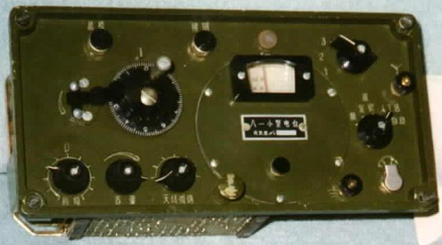
Front Panel Controls
On the bottom left are three controls. The far left control is marked in Chinese and has
the number 0 in the centre. It is connected to a potentiometer. The centre control
indicated volume. Turning it clockwise increases the volume. It too was a potentiometer.
The control on the right rotates through 360 degrees but has markings on the case through
180 degrees. It is connected to a small variable capacitor and is probably for adjusting
the antenna.
Above these controls is the main tuning control. It has a pressure clamp to hold the dial
fast. On a new set, such as this, it worked perfectly. It is, however something that I
think time and use would make a less effective clamp. Above this control are two smaller
controls which are connected to switches. They are 3/8 inch in diameter and not that easy
to turn. One switch is connected to the dial light and derives power from the 1 1/2 volt
battery. I could not identify what the other switch was for. Both have contacts which are
easily bent. The light switch when turned, did nothing until it was pushed in. I think the
object was to have the light available for tuning but not on until the switch button was
depressed. To the right is the main tuning dial and window. The window is lighted, as
mentioned. Three scales are visible in the window.
On the upper right side is a 3 position switch marked 1, 2 and 3 which is probably the
band switch. Below this is another control, a 5 position rotary switch. This seems to be a
sort of function control, Off and whatever else. (The position on the far left put the
switch rotator in contact with an empty space so it must have been the off position.)
Below this is the jack for the head phone connection. Two more items are on the front
panel, screw terminals with the symbols for antenna and ground.
Interior Construction
The set is modular in construction and is made up of circuit boards which can be replaced
if one is found to be defective. All controls are mounted on the front panel and the
modules are mounted on the front panel or a metal frame, similar to the Japanese sets of
WW II. Were it not for the transistors, one would think one was looking at a late war
Japanese set.
The centre area of the set contains the three gang tuning capacitor. It is the same
capacitor as was used in the transmitter. A worm gear meshes with a gear that turns the
capacitor. At the other end is another gear train which turns the tuning dial. Very rugged
construction and probably capable of withstanding rough handling.
There are three tuning modules mounted on top of the set. Another control, the band
selector switch, is mechanically linked to three rotary switches, one per tuning module.
Each of the three modules had three coils, the rotary switches and assorted capacitors,
resistors and other items, believed to be capacitors, which appeared to be adjustable
through access ports on the top of the module covers. These appeared to have been set at
the factory and were not really designed for field repairmen to work on. They were sealed
in position at the factory with a form of glue.
There are two other modules, one on the side which had three IF transformers but were not
adjustable as the tops had been sealed with solder at the factory. This module also had a
plug in crystal which was marked 500 kHz. There were three transistors, 10 capacitors and
23 resistors. The capacitors were in metal cans and were the PC board mounting type. The
resistors were 1/4 watt resistors. There were two other items, both in metal cans, one of
which had two leads so I assume it was a capacitor. This module was electrically connected
to the potentiometer on the front panel which was also connected to ground.
The second module was on the bottom and had two inter-stage transformers, 15 capacitors
that I could see, at least one transistor and numerous resistors. This module was in such
a position that the parts could not easily be seen. There were at least 6 resistors. Most
of the capacitors had insulated sleeves over them to shield them from one another.
Unlike the Type 139 A set, in which the final component was a square metal can that
plugged in to a socket, this unit had no plug in can. The space was there and there were
mounting posts but no component.
Operating Characteristics, Receiver
The tuning dial was graduated in three scales, one from 1.5 to 3.6, the second from 3.6 to
8.5 and the third from 8.5 to 18.0. I assume these are megacycles. Most of the older
Chinese tactical sets operated on 2 to 12 Megacycles. Other characteristics are not
currently available.
Back to Communication Equipment of The North
Vietnamese Army and the Viet Cong.
Army Radio Sales Co. Home Page.