|
|
General description The Chinese Type 139 A Radio Receiver is also late Vietnam war, if in fact it was part of the conflict. It is probably the replacement for the Type 139 Radio Receiver which was a tube set and was powered by a 90 volt dry cell and 1.5 volt dry cells. As of September 1968, none of the R 139A sets had been captured by US forces to the best of my knowledge. This particular set had a serial number of 70 1917. It was speculated that it was made in 1970 and was really set number 1917. This has not been confirmed by any source. If in fact it was made in 1970, it would have entered the Vietnam Conflict in 1971 or 1972, just as the U.S was pulling out and the Technical Intelligence effort ceased to function. |

Physical Description
The set is 10 inches wide, 3 and 1/2 inches deep and 5 inches high.The battery box and
four rubber feet add another two inches to the set, making the overall height 7 inches.
The weight, with out batteries is approximately 6 lbs., more with all 7 batteries in
place. There are sling swivels on either side, indicating that it was designed to be
carried over the shoulder, similar to a Ladies handbag.
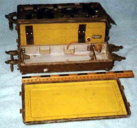
Spring loaded snap catches (4) hold the front panel cover on the set. An additional;
four snap catches hold the battery box on the bottom. The battery box is hinged and can
not be completely separated from the radio.
This set is all solid state and is powered by 7 D cells, providing 9 volts and 1 1/2
volts. The radio is removed from the case by unscrewing four captive screws and then
sliding the radio out of the case. Difficult to do as there are no real handles, only one
knob for pulling. The set tends to stick to the rubber gasket and the power plug is a
tight fit in the connecting socket. This is probably due to age. Once out of the case,
there is an extension of the power cable and plug which plugs into the set and allows it
to be used with the batteries in the battery case while the set is being worked on. This
was no doubt inspired from looking at the Japanese radios of
WW II. There are provisions on the front and the side for a pair of headphones to be used.
|
|
The plug sockets are smaller than the standard 1/4 inch and larger than
the standard mini plugs available in the USA, which means the original headphones must be
obtained or a means of rewiring developed for use with US style plugs. The headphone jack
on the side panel and on the front panel are encased in a plastic shield which makes the
set water tight. It also makes re-wiring almost impossible with out damaging the seals. Front
Panel Controls |
Above these controls is the main tuning control. It has a screw down clamp to hold the dial fast however this did not seem to be working. Above this control are two smaller controls which are connected to switches. They are 3/8 inch in diameter and not that easy to turn. One switch is connected to the dial light and derives power from the 1 1/2 volt battery.(On this set, the dial light was burned out), I could not identify what the other switch was for. Both have contacts which are easily bent. The light switch when turned, did nothing until it was pushed in. Either the contacts were bent or the object was to have the light available for tuning but not on until the switch button was depressed. To the right is the main tuning dial and window. The window is lighted, as mentioned. Three scales are visible in the window.
On the upper right side is a 3 position switch marked 1, 2 and 3 which is probably the band switch. Below this is another control, a 5 position rotary switch. This seems to be a sort of function control, Off and whatever else.(The position on the far left put the switch rotator in contact with an empty space so it must have been the off position.) Below this is one of the two jacks for the head phone connection. Two more items are on the front panel, screw terminals with the symbols for antenna and ground. Another screw terminal is located on the top of the set. At first I thought it might be for an antenna connection for when the set was installed in a vehicle. A second jack socket was located on the side which was for a second set of headphones.
|
|
Interior Construction The set is modular in construction and is made up of circuit boards which can be replaced if one is found to be defective. All controls are mounted on the front panel and the modules are mounted on the front panel or a metal frame, similar to the Japanese sets of WW II. Were it not for the transistors, one would think one was looking at a late war Japanese set. |
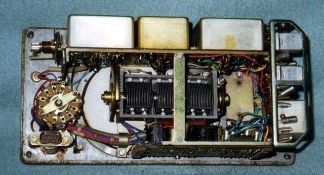
The centre area of the set contains the three gang tuning capacitor. A worm gear meshes with a gear that turns the capacitor. At the other end is another gear train which turns the tuning dial. Very rugged construction and probably capable of withstanding rough handling.
There are three tuning modules mounted on top of the set. Another control, the band selector switch, is mechanically linked to three rotary switches, one per tuning module. Each of the three modules had three coils, the rotary switches and assorted capacitors, resistors and other items, believed to be capacitors, which appeared to be adjustable through access ports on the top of the module covers. These appeared to have been set at the factory and were not really designed for field repairmen to work on. They were sealed in position at the factory with a form of glue.
There are two other modules, one on the side which had three IF transformers but were
not adjustable as the tops had been sealed with solder at the factory. This module also
had a plug in crystal which was marked 500 kHz. There were three transistors, 10
capacitors and 23 resistors. The capacitors were in metal cans and were the PC board
mounting type. The resistors were 1/4 watt resistors. There were two other items, both in
metal cans, one of which had two leads so I assume it was a capacitor. This module was
electrically connected to the potentiometer on the front panel which was also connected to
ground.
The second module was on the bottom and had two inter-stage transformers, 15 capacitors
that I could see, at least one transistor and numerous resistors. This module was in such
a position that the parts could not easily be seen. There were at least 6 resistors. There
was evidence of corrosion on some of the parts. Most of the capacitors had insulated
sleeves over them to shield them from one another.
The final component was a square metal can that plugged in to a socket. Contact was made by two screws that fit into sockets. This did not seem to be the best method of plugging something in but presumably it worked.
Operating Characteristics
The tuning dial was graduated in three scales, one from 1.5 to 3.6, the second from 3.6 to
8.5 and the third from 8.5 to 18.0. I assume these are megacycles. Most of the older
Chinese tactical sets operated on 2 to 12 Megacycles. Other characteristics are not
currently available.
Tactical Employment:
The Chinese military is not as dependent on radio communication as the American army is.
In many cases, the subordinate units have a receiver only so they can listen for
instructions but can not ask questions or respond. This set can be used in a weather
warning role as well as listening for coded messages.
Strengths and weaknesses
Principle strength of the set is it's compact size, rugged construction and it's ability
to run on flash light D cells, found in most every hardware store. Major weakness is the
fact that it is not easily repaired. Removal of either of the two side or lower modules
would require considerable labour. Replacement of one or more of the tuning modules would
require removal of all three so that the shaft for the rotary switches can be withdrawn.
In addition, while there are three separate modules, they are all built on one printed
circuit board. Any major damage to a tuning module requires replacement of all three. It
is my opinion that this set is basically a throw away set. If anything breaks down, throw
it away and get a new one.
Collector Value
Difficult to place a value on this set. It is not readily identifiable as part of the
North Vietnamese or Viet Cong arsenal during the period of the U.S. effort during the
Vietnam War. Probably worth about $150 to $200.00 to a serious collector. Would be worth
more if the headset were included as well as antenna, technical manual and a schematic. An
interesting piece of Radio History of the Chinese Armed Forces. It is also one of the
first Chinese military sets to use transistors, a step forward for the Chinese Radio
industry.
Back to Communication Equipment of The North
Vietnamese Army and the Viet Cong.
Army Radio Sales Co. Home Page.