|
|
There are at least three "home brew" radios known to exist. The first was shown in the July 1967 T.I.B. and was a transmitter and receiver built into a chassis that fitted into a Cal. .50 ammunition can. Very little effort was given to an analysis of this set. The voltages, the frequency range and power requirements were about all that was listed. One of my projects was to build a copy of the set. I ended up with the standard 6L6 transmitter circuit, but with a different 1.5 volt filament tube, using a coil wound on a section of cardboard tube with taps that fed to an octal tube socket. |
Changing the jumper wire in the socket changed the number of turns in the plate coil, as must have been done on the original. The set was tested by Jim Kearman at the time he worked for the ARRL and it worked. The receiver was a two tube set with a 1S5 detector and a 1T4 for an amplifier. When all else fails to get a radio working, I send it to Don Dean in Sarasota and he managed to get it working for me. The original set has been lost so it can not be studied in any detail.
In the early stages of the Vietnam conflict, the Viet Minh and later the Viet Cong were equipped with a variety of leftover W.W.II weapons supplemented by what they could fabricate in their underground factories. Communication equipment was also in short supply. This began to change and by 1967, the Viet Cong and North Vietnamese Army were equipped with sets made in China. The X06, copied in part from the US WW II SCR694, the Mercury Talk Set which resembled a W.W.II Japanese set and the Type 63 backpack set which looked like an ANIPRC-1O mounted in a BC-boo were among the sets that were captured. Occasionally, a Soviet radio would show up but these were few and far between.
Captured radio sets were first evacuated to the nearest Radio Research Unit, the local version if the N.S.A. and responsible for signal intercept operations where information of immediate intelligence value was recorded. Primarily this was frequency and range of the set. When Radio Research finished with the set it was evacuated to the Combined Material Exploitation Centre (C.M.E.C.) for detailed technical intelligence exploitation. In most cases this resulted in the destruction of the set as all the components were removed and the remaining hulks were sent to the scrap yard. Samples of each set were placed in the C.M.E.C. museum and used for training new intelligence personnel. There were very few radios used by the Viet Cong, fewer captured by U.S. Forces and very few came back to the states in private hands. Today these sets are very scarce.
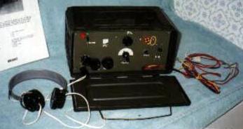
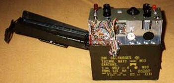
In 1988, while a guest at the dedication of the new Foreign Material Intelligence Complex at Aberdeen Proving Ground, I went through the Ordnance Museum. The C.M.E.C. Museum in Vietnam had been evacuated and was now part of the Ordnance Museum. Many of the enemy weapons I had helped to evacuate were on display. One of the more unusual items was a Viet Cong "Home Brew" Radio built to fit into a standard U.S. 30 cal ammunition can.! took several photos through the glass case but these photos revealed very little other than sub-miniature tubes were used. Several years later through the efforts of Bill Seaby, the set was taken from the case and a set of detailed photographs was sent to me.
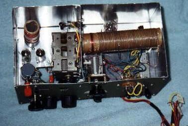
The set was originally designed to be two radios on one chassis. Only one side was wired so it is open to speculation what the other side was to become. One part was a shielded variable capacitor, tube and coil. The remainder had four tube sockets, two variable capacitors and a large hole in the chassis, possibly for a coil. The side that was wired seemed to be a regenerative detector with three stages of audio amplification. There was one tube ahead of the detector which could have been an RF amplifier but there was no coil for such a stage. Sub-miniature sockets were used throughout the set. The coil for the receiver was wound on the base of an octal tube and an octal tube socket was mounted in the centre of the chassis. Without any tubes in the set and a broken coil, the set was inoperable and simply a display item. Without being able to examine the set in detail, it was impossible to trace the wiring diagram but it appeared to be a regenerative detector with a capacitor coupled amplification system. The resistors went either to a bus bar wire or were grounded to the chassis. The final stage was connected to an output transformer which seemed to be for the purpose of isolating B+ from the chassis. The transformer output was grounded to the chassis and a red wire went to the headphone socket.
|
|
I decided that t it would make an interesting project to duplicate this set and see if it could be made to work. The original set was made from a series of panels held together by brass machine screws. I obtained an ammunition can and began the process of making a cardboard chassis. Side panels, back panel and front panel were then cut from aluminium. The centre panel and shields were also cut from aluminium. A template for the centre panel was laid out, after all the parts were assembled and a second template was made for the front panel. Finding parts that duplicated the original set was difficult. Miniature 7 pin tube sockets of the same colour as the original were finally located as were other parts. Then the main chassis and all panels were taken to a local metal working shop where holes and cut-outs were done and the chassis was assembled. |
The tuning capacitor was mounted on the centre divider panel and a local machine shop was contacted to turn a dial/drive pulley. Once the mechanical work was completed, the other components were mounted and the set began to take shape. The filaments were wired first, one lead to chassis and one lead to the main power switch. The chassis was A+ and B-. B+ was then wired to a bus bar wire and the output transformer was wired into the circuit. This set does not have a lot of room for wires and the lead to the headphone socket was buried under the other parts. The amplifier section was then wired. Resistors with proper values that resembled the original set were easy to find but capacitors were difficult. I used modern capacitors as I felt they were more reliable.
The detector portion was then wired and coupled to the amplification stages through an RF choke. Since I could not find a circuit for an RF amplifier that did not use a coil, I decided to eliminate the first tube. The coil was wound on an octal tube base with a cardboard insert and plugged into the socket. The set was powered up and nothing happened! I had a local collector go over the set and we reached the conclusion the problem was in the detector circuit. After several further attempts to get the set operational I gave in and took the set to Don Dean in Sarasota who repairs old time radios. Don went over the set and finally got it to work. He rewired the coil and eliminated two stages of amplification. The end result was that a I S 5 tube was used for the detector and a 1T4 was used as an amplifier. In Sarasota, with a good antenna the set picked up 5 local AM Stations. In Largo it got three stations using a 30 foot copper wire antenna. The set now sits on the shelf as part of my Technical Intelligence Museum Displays.
Several conclusions were reached as a result of this project. The first is that the set could have been made much smaller and still put in an ammo can and there would have been room for batteries, head set and antenna. The second conclusion was that it would have been easier to use a long strip of aluminium bent to shape than to have made it from separate panels. Of course, the Viet Cong may not have had a long strip of aluminium and were forced to use small scraps for the chassis. It is questionable if the original set ever saw service or was captured when U.S. Forces overran the underground factory. It is also possible that they could not get the original set to work which is why it was dropped and the other side was never wired. Shortly after this article was published in ELECTRIC RADIO Magazine, I received several letters with circuits for an RF amplifier that did not require a coil.
Third confirmed Ammo Can Radio
The third known "Home brew" set was shown in a photograph sent to me by Jan
Schrader from the collection of photographs he brought home from Vietnam. The set was
shown next to a crate of ammunition which looked like it was for a WW II Japanese
howitzer. There was a Chinese howitzer that used the same calibre ammunition as the WW II
Japanese gun. I assume that the radio was made in the 1950's or early 1960s and captured
very early in the war. It was not mentioned in the 1967 T.I. B. This radio set has
disappeared and all that remains of it is the photograph. No effort has been made to make
a reproduction of the set.
Fourth confirmed and Documented Home Brew Set
This set was described in the July 1967 T.I. B. It was a handmade radio transmitter and
receiver which was an AM set capable of transmitting and receiving CW only. It was
reported to have a range of approximately 20 Miles. It weighted 15 lbs. and was in a metal
chest 11 inches by 9 inches by 6 1/2 inches. The receiver required 1.5 volts and 90 VDC
and the transmitter required 1.5 volts and 180 VDC. The radio was made in two units,
receiver and transmitter. Power was supplied via a four pin plug and wired into the
transmitter. Presumably there was a connection under the panel to the receiver.
The set covered 3.8 to 6.4 MC and produced approximately 2 watts. The T.I.B. had a picture
of the set but no further details.
|
|
Several More "Almost
Runs" The first set which I call an "Almost ran" set started as an attempt in 1988 to reconstruct a VC ammo can radio that I saw on display at the Ordnance Museum. Photographed from out side the display case, I could not tell very much but knew what the top panel controls were and saw 7 pin miniature tube sockets. I obtained an ammo can at a local surplus store. I then made up a cardboard model of what was wanted and drew in the diagram of all the parts. I then contacted a machine shop to fabricate a chassis, and drill holes for tube sockets. |
Once this was completed, I took it home and began to mount the components. I had to rig up some form of pulley arrangement to get the dial drive to turn the receiver tuning capacitor. I divided the set into a receiver section and a transmitter section. At this time my knowledge of radio circuits was limited and I took the set to Craig Smith and asked him to "wire it so it looked good". The set then sat on the shelf with no further work being done on it other than to make a battery pack for it that looked reasonable.
I then decided that I would make up some accessories for it. An antenna holder was made from hardware store nuts and bolts, scrap wood and some sections of a bamboo rod. Next came a similar set up for the ground contact and some old wooden boxes were converted into "spares boxes" holding tubes, crystals, coils and a few other items. The set looked pretty realistic, even if it was not really wired to work.
I ran across a set of plans for a vibrator power supply that worked from either 110 volts or a 6 volt battery. One day I was at Vulcan Surplus in Tampa and managed to get all the parts needed for a vibrator power supply. The transformer did not have a 110 volt winding in the primary but that was not a major problem. Again I drew up a cardboard pattern for a power supply that would fit into a .50 cal size ammo can. I got all the components mounted and wired. I was not certain if I had done it correctly and wanted someone to check it out for me before I put power to it. No one locally could do anything on it.
The local outfit that works on old time car radios refused to even look at it as it was not an "Old time Car Radio" It too joined the R/T unit sitting on the shelf.
As previously mentioned, a friend in the Baltimore area managed to get the Ordnance Museum director to take the original set out of the museum case and he took some very detailed photos of the set. The original model was nothing like I had imagined and my re-construction was completely different than the original. I decided to start over. I made up a new template and built a second set. This set worked and is on display. The original attempt was relegated to the corner to collect dust.
In 1997, some 10 years after I had started the original project, I became acquainted with Mark Gluch in the Detroit area. I contacted him, and sent the vibrator power supply up to him. He managed to get it working and sent it back to me. He got the vibrator portion working but it quickly burned out several of the capacitors as the secondary of the power transformer was incorrectly wired. Replacing the capacitors that were damaged, the power supply came to life. Running from a 6 volt storage battery, it puts out 375 volts and 150 volts with no load on it. Now what? I started wondering if the receiver and transmitter could be made to work.
I dug out the original set and tore apart the wiring in the transmitter and rewired it as the standard classic 6L6 transmitter that was described in the book, "GOLDEN CLASSICS OF YESTERYEAR" by Dave Ingram,K4TWJ. Of course the 6L6 tube was too big for the set as built so I planned to use a 6V6 tube which is about an inch shorter. I figured if the 6V6 was good enough for the WW II British Para set, it would work here. Once rewired, I sent it back up to Mark Gluch to see if it was working.
The receiver was a bit more of a challenge. I found a circuit in the RCA Receiving Tube manual that looked like it would work. It called for 12 volt, 35 volt and 50 volt filament tubes running from 110 VAC. I managed to come up with 6 volt miniature tubes that would work and began to redesign and re wire the set. The tube line up that was selected was the 6 BE 6, Penta-grid Converter, 6 BA 6 as IF amplifier, 6 AV 6 as Diode detector, Audio Amp and AVC and a 6 AQ 5 as the power amplifier.
While this set never saw service in the Vietnam War, it is representative of the type radios that could be built in clandestine underground factories, with a minimum of tools. Tin shears, a power drill, a hole punch, soldering iron, screwdriver, files and a volt meter were about all that I had to work with, when I assembled this radio.
Another almost ran set
In the process of researching circuits that were in existence and simple to build in the
1945 to 1960 time frame, I came on a two tube regenerative circuit called the "Doerle
Globe Trotter". I constructed a small set about 4 inches by 2 inches by 10 inches
which would fit into the standard AK-47 style ammo bandoleer. The battery pack was the
same size and antennas, headphone and other accessories fit into the side pockets. It
worked reasonably well for the broadcast bands in central Florida. With a little
experimentation, it could have been made even smaller. I used a Type 19 tube. Since that
time, I have found a report on a Japanese WW II radio called the 1568 radio which used
three 1 T 4 tubes. A similar miniature tube could have been used for a smaller set. This
set was about the same size as the 702 series radios.
The conclusions I made from constructing these "almost runs" is that all sorts of radios could have been made by the Viet Cong and probably were. They were limited only by their imagination and availability of parts. A second conclusion is that anyone trying to collect Chinese/NVA/VC radios needs to be aware that replicas can be easily made of the VC ammo can radios. Unless well documented, the radio is worth the price of the parts and a small amount for the labour, depending on how much labour is involved.
Back to Communication Equipment of The North
Vietnamese Army and the Viet Cong.
Army Radio Sales Co. Home Page.